Mitsubishi Montero (1991+). Manual - part 13
immediately before connections are made. This will keep entry of air
and moisture to a minimum.
CONNECTING LINES AND FITTINGS
A new gasket or "O" ring should be used in all instances when
connecting lines or fittings. Dip "O" ring in new refrigerant oil and
ensure it is not twisted during installation. Always use 2 wrenches to
prevent damage to lines and fittings.
PLACING SYSTEM IN OPERATION
After component service or replacement has been completed and
all connections have been made, evacuate system thoroughly with a
vacuum pump. Charge system with proper amount of refrigerant and
perform a leak test. See REFRIGERANT OIL & R-12 SPECIFICATIONS chart
in this section for system capacities. Be sure to check all fittings
that have been opened. After system has been leak tested, make a
system performance check.
NOTE: Air conditioning systems will not normally need addition of
refrigerant oil unless definite oil loss has occurred due to
ruptured lines, leaking compressor seals, compressor
overhaul or component replacement.
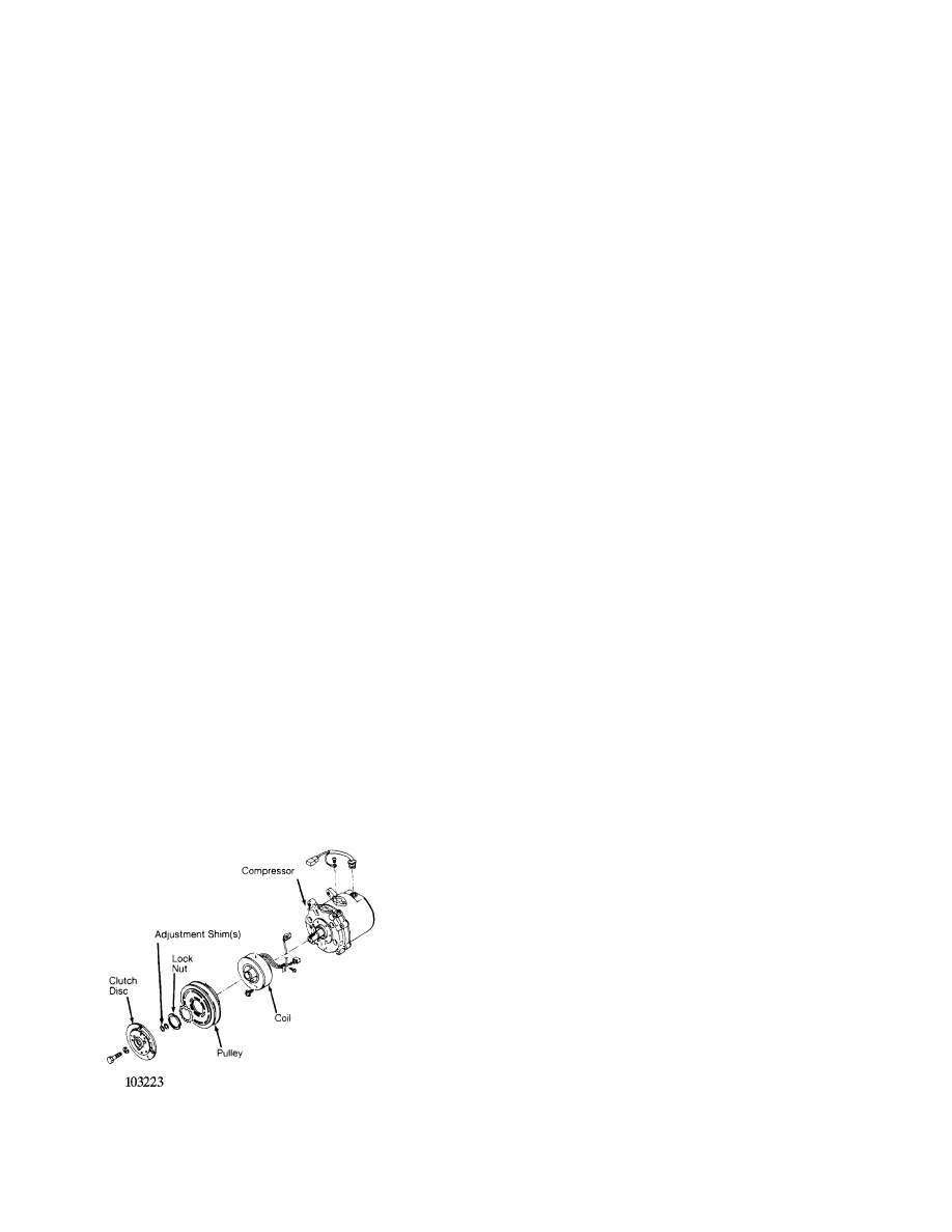
ATSUGI ROTARY VANE CLUTCH R & I
Removal
When replacing compressor clutch, be careful not to scratch
shaft or bend pulley. When removing center bolt, hold clutch disc with
Clutch Holder (KV99231010). Using Hub Puller (KV998VR001 &
KV99231010), remove clutch disc. When removing pulley, remove lock nut
with Hub Socket (KV99235160).
Installation
Wipe oil off clutch surface. Adjust disc pulley clearance to
.012-.024" (.3-.6 mm). Tighten center bolt to 80-104 INCH lbs. (9.1-
11.8 N.m). Tighten clutch lock nut to 22-29 ft. lbs. (29-39 N.m). See
Fig. 1.
Fig. 1: Atsugi Rotary Vane Compressor
Courtesy of Nissan Motor Co., U.S.A.
BOSCH 6-CYL CLUTCH R & I