Mitsubishi Galant (2004+). Manual - part 994


  Index      Mitsubishi     Mitsubishi Galant - service repair manual 2004 year


Search            


Content   ..  992  993  994  995   ..


Mitsubishi Galant (2004+). Manual - part 994


MULTIPORT FUEL INJECTION (MFI) DIAGNOSIS

TSB Revision

MULTIPORT FUEL INJECTION (MFI) <2.4L ENGINE>

13A-793

TROUBLESHOOTING HINTS (The most likely 
causes for this code to be set are:)

• Throttle actuator control motor relay failed.

• Open or shorted throttle actuator control motor 

relay circuit, or connector damage.

• PCM failed.

DIAGNOSIS

Required Special Tools:

• MB991958: Scan Tool (MUT-III Sub Assembly)

• MB991824: V.C.I.

• MB991827: USB Cable

• MB991910: Main Harness A

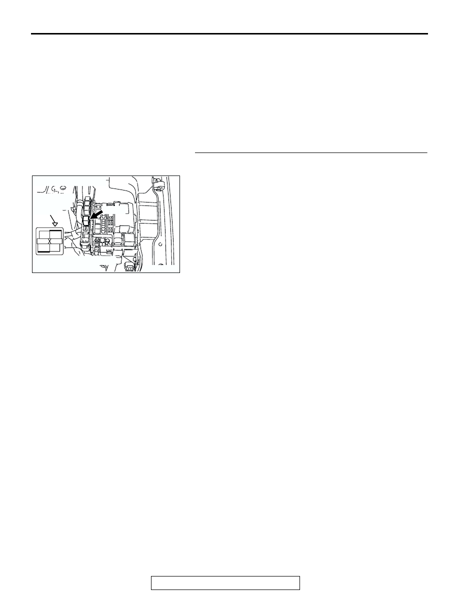
STEP 1. Check harness connector B-14X at throttle 
actuator control motor relay for damage.

Q: Is the harness connector in good condition?

YES : Go to Step 2.
NO :  Repair or replace it. Refer to GROUP 00E, Harness 

Connector Inspection 

P.00E-2

. Then go to Step 14.

AK303887

2

1

3

4

AB

CONNECTOR: B-14X

B-14X

RELAY BOX
TRIANGLE 
MARK

HARNESS CONNECTOR:
COMPONENT SIDE

MULTIPORT FUEL INJECTION (MFI) DIAGNOSIS

TSB Revision

MULTIPORT FUEL INJECTION (MFI) <2.4L ENGINE>

13A-794

STEP 2. Check the throttle actuator control motor relay.

CAUTION

Because it is not possible to distinguish the top and the 
bottom of the throttle actuator control motor relay, inspect 
it with the triangle mark printed on the relay facing upward.
(1) Remove the throttle actuator control motor relay.

(2) Check for continuity between the throttle actuator control 

motor relay terminal No. 2 and No. 3.

• There should be continuity (approximately 70 ohms).

(3) Use jumper wires to connect throttle actuator control motor 

relay terminal No. 3 to the positive battery terminal and 
terminal No. 2 to the negative battery terminal.

(4) Check the continuity between the throttle actuator control 

motor relay terminal No. 1 and No. 4 while connecting and 
disconnecting the jumper wire at the negative battery 
terminal.

• Should be less than 2 ohms. (Negative battery terminal 

connected.)

• Should be open loop. (Negative battery terminal discon-

nected.)

(5) Install the throttle actuator control motor relay.
Q: Is the measured resistance normal?

YES : Go to Step 3.
NO :  Replace the throttle actuator control motor relay.       

Then go to Step 14.

AK303887

2

1

3

4

AB

CONNECTOR: B-14X

B-14X

RELAY BOX
TRIANGLE 
MARK

HARNESS CONNECTOR:
COMPONENT SIDE

1

2

3

4

AK302117AB

THROTTLE ACTUATOR 
CONTROL MOTOR RELAY
SIDE CONNECTOR

1

2

3

4

AK302118

THROTTLE ACTUATOR 
CONTROL MOTOR RELAY
SIDE CONNECTOR

AB

MULTIPORT FUEL INJECTION (MFI) DIAGNOSIS

TSB Revision

MULTIPORT FUEL INJECTION (MFI) <2.4L ENGINE>

13A-795

STEP 3. Measure the power supply voltage at throttle 
actuator control motor relay harness side connector B-14X

CAUTION

Because it is difficult to distinguish the top and bottom of 
the throttle actuator control motor relay connector at the 
wiring harness, inspect it by using triangle mark on the 
junction block as a reference.
(1) Disconnect the connector B-14X and measure at the 

harness side.

(2) Measure the voltage between terminal No. 1 and ground.

• Voltage should be battery positive voltage.

Q: Is battery positive voltage (approximately 12 volts) 

present?
YES : 
Go to Step 4.
NO :  Check harness connector A-13 at intermediate 

connector for damage, and repair or replace as 
required. Refer to GROUP 00E, Harness Connector 
Inspection 

P.00E-2

. If intermediate connector A-13 is 

in good condition, repair it because of open circuit or 
short circuit to ground between battery and throttle 
actuator control motor relay connector B-14X 
(terminal No. 1). Then go to Step 14.

AK303887

2

1

3

4

AB

CONNECTOR: B-14X

B-14X

RELAY BOX
TRIANGLE 
MARK

HARNESS CONNECTOR:
COMPONENT SIDE

2

1

3

4

AK202996

B-14X HARNESS
CONNECTOR:
COMPONENT SIDE

AC

RELAY BOX
TRIANGLE MARK

MULTIPORT FUEL INJECTION (MFI) DIAGNOSIS

TSB Revision

MULTIPORT FUEL INJECTION (MFI) <2.4L ENGINE>

13A-796

STEP 4. Measure the power supply voltage at throttle 
actuator control motor relay harness side connector 
B-14X.

CAUTION

Because it is difficult to distinguish the top and bottom of 
the throttle actuator control motor relay connector at the 
wiring harness, inspect it by using triangle mark on the 
junction block as a reference.
(1) Disconnect the connector B-14X and measure at the 

harness side.

(2) Turn the ignition switch to the "ON" position.

(3) Measure the voltage between terminal No. 2 and ground.

• Voltage should be battery positive voltage.

(4) Turn the ignition switch to the "LOCK"(OFF) position.
Q: Is battery positive voltage (approximately 12 volts) 

present?
YES : 
Go to Step 6.
NO :  Go to Step 5.

STEP 5. Check harness connector B-17X at MFI relay for 
damage.

Q: Is the harness connector in good condition?

YES : Repair harness wire between MFI relay connector 

B-17X (terminal No. 4) and throttle actuator control 
motor relay connector B-14X (terminal No. 2) 
because of open circuit or short circuit to ground. 
Then go to Step 14.

NO :  Repair or replace it. Refer to GROUP 00E, Harness 

Connector Inspection 

P.00E-2

. Then go to Step 14.

AK303887

2

1

3

4

AB

CONNECTOR: B-14X

B-14X

RELAY BOX
TRIANGLE 
MARK

HARNESS CONNECTOR:
COMPONENT SIDE

2

1

3

4

AK303888AB

B-14X HARNESS 
CONNECTOR: 
COMPONENT SIDE

RELAY BOX
TRIANGLE MARK

AK303806

2

1

3

4

AB

CONNECTOR: B-17X

B-17X

RELAY BOX
TRIANGLE 
MARK

HARNESS CONNECTOR:
COMPONENT SIDE


Content   ..  992  993  994  995   ..