Mitsubishi Galant (2004+). Manual - part 982


  Index      Mitsubishi     Mitsubishi Galant - service repair manual 2004 year


Search            


Content   ..  980  981  982  983   ..


Mitsubishi Galant (2004+). Manual - part 982


MULTIPORT FUEL INJECTION (MFI) DIAGNOSIS

TSB Revision

MULTIPORT FUEL INJECTION (MFI) <2.4L ENGINE>

13A-745

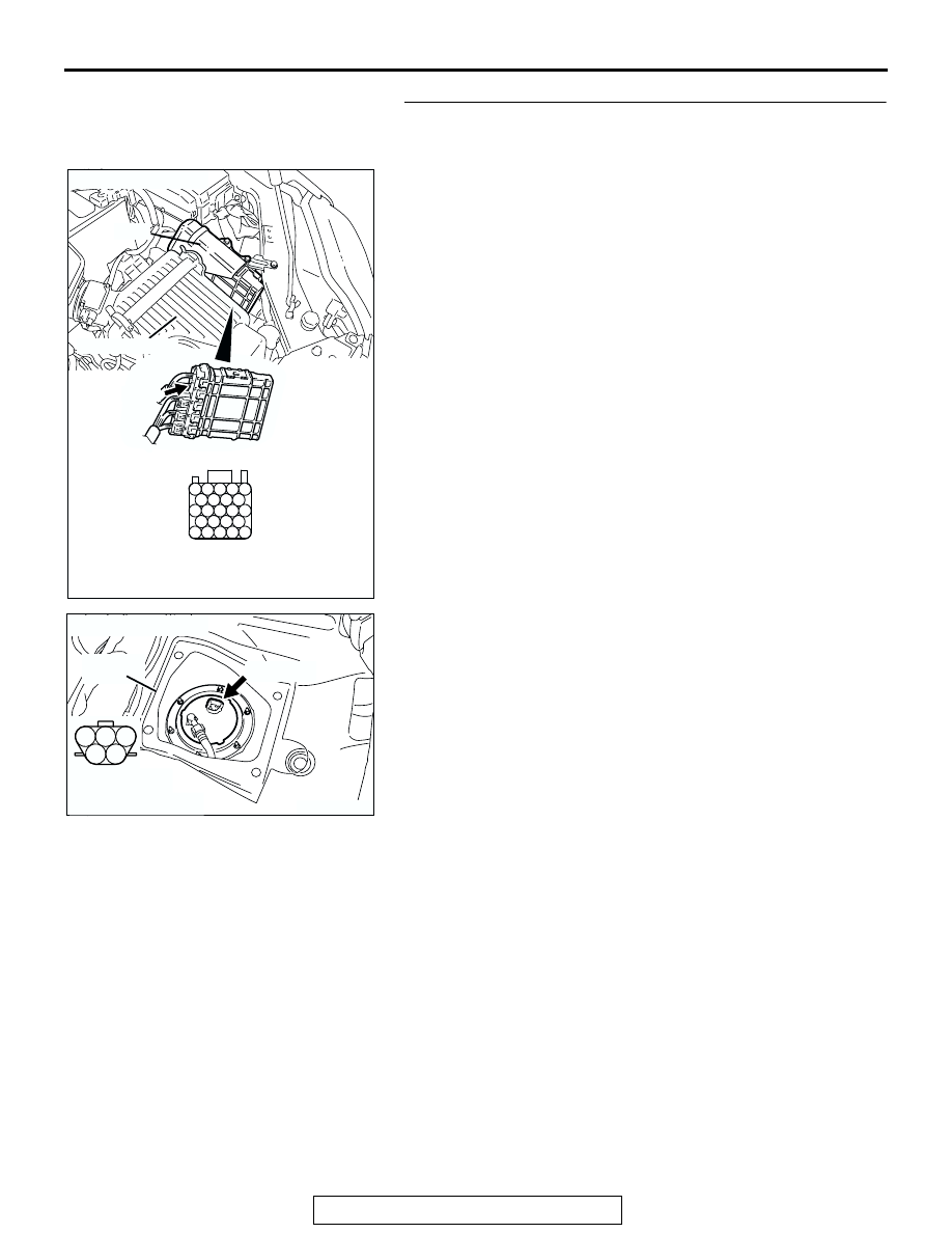
STEP 5. Check for open circuit and short circuit to ground 
between PCM connector B-20 (terminal No. 24) and fuel 
level sensor (main) connector D-18 (terminal No. 2).

NOTE: Check harness after checking intermediate connector 
C-25. If intermediate connector is damaged, repair or replace it. 
Refer to GROUP 00E, Harness Connector Inspection 

P.00E-2

Then go to Step 9.
Q: Is the harness wire in good condition?

YES : Go to Step 6.
NO :  Repair it. Then go to Step 10.

AK303092

25

21

24 23 22

29 28 27 26

34 33 32 31 30

38 37 36 35

43 42 41 40 39

CONNECTOR: B-20

B-20

PCM

AB

HARNESS CONNECTOR: 
COMPONENT SIDE

AIR CLEANER

AK303840

1

2

3

4

5

SERVICE
HOLE

AB

CONNECTOR: D-18

D-18 (GR)

HARNESS 
CONNECTOR: 
COMPONENT SIDE

MULTIPORT FUEL INJECTION (MFI) DIAGNOSIS

TSB Revision

MULTIPORT FUEL INJECTION (MFI) <2.4L ENGINE>

13A-746

STEP 6. Check harness connector D-17 at fuel level sensor 
(sub) for damage. 

Q: Is the connector in good condition?

YES : Go to Step 7.
NO :  Repair or replace it. Refer to GROUP 00E, Harness 

Connector Inspection 

P.00E-2

. Then go to Step 10.

STEP 7. Check for open circuit between fuel level sensor 
(sub) connector D-17 (terminal No. 1) and fuel level sensor 
(main) connector D-18 (terminal No. 2).

Q: Is the harness wire in good condition?

YES : Go to Step 8.
NO :  Repair it. Then go to Step 10.

STEP 8. Check the fuel pump module.

Check to see if the fuel pump module is normal. Refer to 
GROUP 54A, Chassis Electrical 

− Combination Meters Assem-

bly and Vehicle Speed Sensor 

− On-Vehicle Service − Fuel 

Level Sensor Check 

P.54A-108

.

Q:  Is the fuel pump module normal?

YES : Go to Step 9.
NO :  Replace the fuel pump module. Then go to Step 10.

AK303878

1

2

AB

CONNECTOR: D-17

D-17

HARNESS 
CONNECTOR:
COMPONENT SIDE

AK303878

1

2

AB

CONNECTOR: D-17

D-17

HARNESS 
CONNECTOR:
COMPONENT SIDE

AK303840

1

2

3

4

5

SERVICE
HOLE

AB

CONNECTOR: D-18

D-18 (GR)

HARNESS 
CONNECTOR: 
COMPONENT SIDE

MULTIPORT FUEL INJECTION (MFI) DIAGNOSIS

TSB Revision

MULTIPORT FUEL INJECTION (MFI) <2.4L ENGINE>

13A-747

STEP 9. Check the trouble symptoms.

(1) Carry out a test drive with the drive cycle pattern. Refer to 

Diagnostic Function 

− OBD-II Drive Cycle − Procedure 6 − 

Other Monitor 

P.13A-5

.

(2) Check the diagnostic trouble code (DTC).
Q: Is DTC P0461 set?

YES : Replace the PCM. Then go to Step 10.
NO :  It can be assumed that this malfunction is intermittent. 

Refer to GROUP 00, How to Use 
Troubleshooting/Inspection Service Points 

P.00-6

.

STEP 10. Test the OBD-II drive cycle.
(1) Carry out a test drive with the drive cycle pattern. Refer to 

Diagnostic Function 

− OBD-II Drive Cycle − Procedure 6 − 

Other Monitor 

P.13A-5

.

(2) Check the diagnostic trouble code (DTC).
Q: Is DTC P0461 set?

YES :  Retry the troubleshooting.
NO :  The inspection is complete.

DTC P0506: Idle Control Sytem RPM Lower Than Expected

CAUTION

If DTC P0506 has been set, TCL related DTC 
U1120 is also set. After P0506 has been diag-
nosed, don't forget to erase DTC U1120.

.

TECHNICAL DESCRIPTION

• The amount of air taken in during idling is regu-

lated by the opening and closing of the throttle 
valve.

• The PCM checks the difference between the 

actual engine speed and the target engine speed.

.

DESCRIPTIONS OF MONITOR METHODS
Difference between actual and target idle speed is 

over the specified value.

.

MONITOR EXECUTION
Continuous

.

MONITOR EXECUTION CONDITIONS (Other 
monitor and Sensor)

Other Monitor (There is no temporary DTC stored 

in memory for the item monitored below)

• Misfire monitor

• Exhaust gas recirculation (EGR) system monitor

• Fuel system monitor

Sensor (The sensor below is determined to be 

normal)

• Mass airflow sensor

• Engine coolant temperature sensor

• Intake air temperature sensor

• Barometric pressure sensor

• Throttle position sensor

.

MULTIPORT FUEL INJECTION (MFI) DIAGNOSIS

TSB Revision

MULTIPORT FUEL INJECTION (MFI) <2.4L ENGINE>

13A-748

DTC SET CONDITIONS

Logic Flow Chart

.

Check Conditions

• Under the closed loop idle speed control.

• The engine coolant temperature is more than 

77

°C (171°F).

• Battery positive voltage is higher than 10 volts.

• Power steering pressure switch: OFF

• Volumetric efficiency is lower than 40 percent.

• Barometric pressure is higher than 76 kPa (22.4 

in.Hg).

• Intake air temperature is higher than −10°C 

(14

°F).

• 60 seconds have elapsed from the start of the 

previous monitoring.

• Target throttle actuator control motor position is 

more than 255 steps.

Judgment Criteria

• The actual idle speed is more than 100 r/min 

lower than the target idle speed for 12 seconds.

.

OBD-II DRIVE CYCLE PATTERN
Refer to Diagnostic Function 

− OBD-II Drive Cycle − 

Procedure 6 

 Other Monitor 

P.13A-5

.

.

TROUBLESHOOTING HINTS (The most likely 
causes for this code to be set are:)

• Throttle valve area is dirty.

• PCM failed.

END

NO

NO

NO

YES

YES

YES

MALFUNCTION

GOOD

START

CALCULATE      Ne

MONITORING

CONDITIONS

   Ne = (ACTUAL-Ne) – (TARGET-Ne)
Ne: ENGINE SPEED

    Ne < –100 r/min OR

> 200 r/min

HAVE 12secs PASSED?

AK302165


Content   ..  980  981  982  983   ..