Mitsubishi Galant (2004+). Manual - part 940


  Index      Mitsubishi     Mitsubishi Galant - service repair manual 2004 year


Search            


Content   ..  938  939  940  941   ..


Mitsubishi Galant (2004+). Manual - part 940


MULTIPORT FUEL INJECTION (MFI) DIAGNOSIS

TSB Revision

MULTIPORT FUEL INJECTION (MFI) <2.4L ENGINE>

13A-577

Judgement Criteria

• When the EGR valve opens to the prescribed 

opening, when intake manifold pressure fluctua-
tion width is lower than 2.0 kPa (0.59 in.Hg).

.

OBD-II DRIVE CYCLE PATTERN
Refer to Diagnostic Function 

− OBD-II Drive Cycle − 

Procedure 5 

− Exhaust Gas Recirculation (EGR) 

System Monitor 

P.13A-5

.

.

TROUBLESHOOTING HINTS (The most likely 
causes for this code to be set are: )

• Contaminated EGR valve and EGR passage.

• EGR valve (stopper motor) failed.

• Open or shorted EGR valve (stopper motor) cir-

cuit, or connector damage.

• Manifold absolute pressure sensor failed.

• PCM failed.

DIAGNOSIS

Required Special Tools:

• MB991958: Scan Tool (MUT-III Sub Assembly)

• MB991824: V.C.I.

• MB991827: USB Cable

• MB991910: Main Harness A

STEP 1. Check the EGR system

Refer to GROUP 17, Emission Control System 

− Exhaust Gas 

Recirculation (EGR) System 

− General Information 

P.17-91

.

Q: Are there any abnormalities?

YES : Repair it. Then go to Step 3.
NO :  Go to Step 2.

STEP 2. Using scan tool MB991958, check data list item 95: 
Manifold Absolute Pressure Sensor.

CAUTION

To prevent damage to scan tool MB991958, always turn the 
ignition switch to the "LOCK" (OFF) position before con-
necting or disconnecting scan tool MB991958.
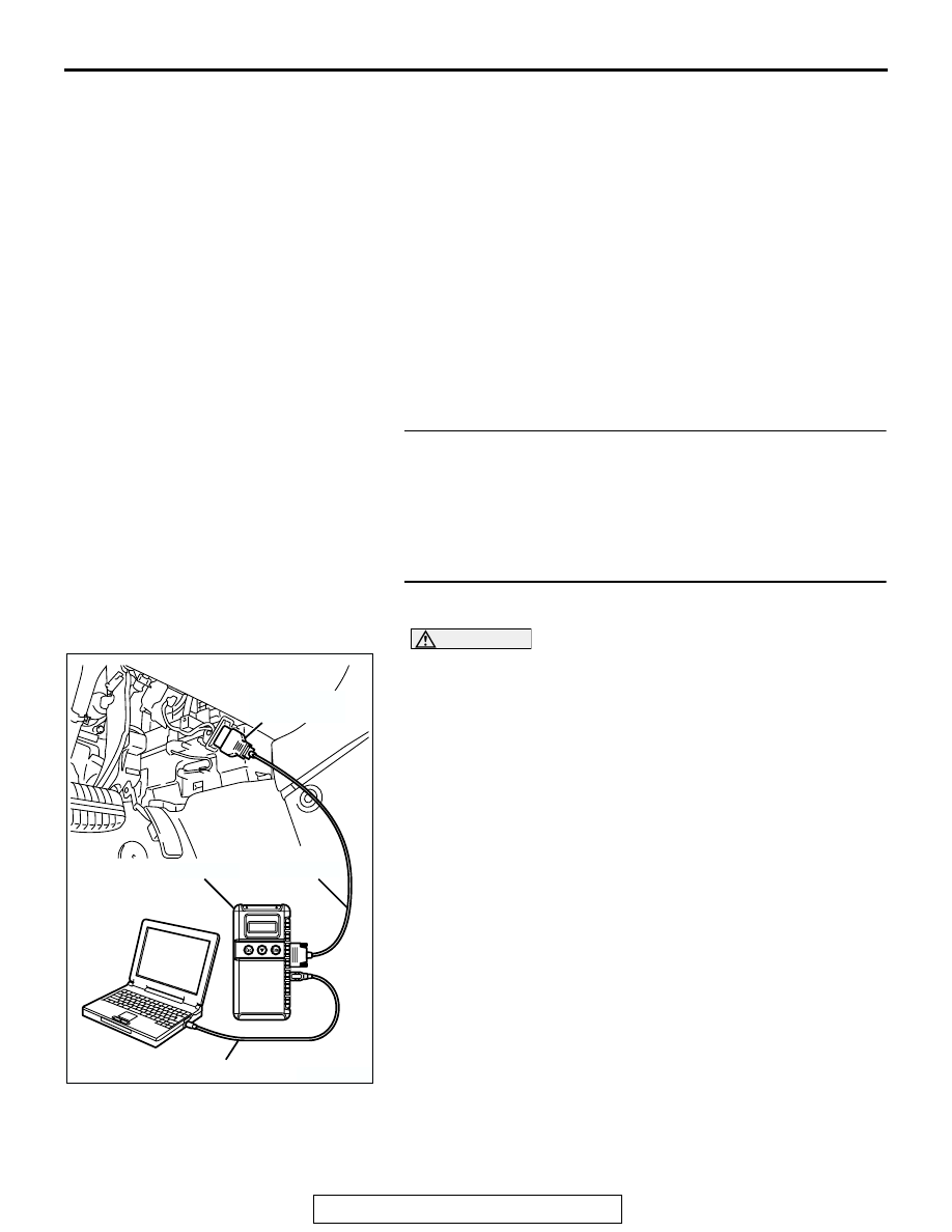
(1) Connect scan tool MB991958 to the data link connector.
(2) Start the engine and run at idle.

(3) Set scan tool MB991958 to the data reading mode for item 

95, Manifold Absolute Pressure Sensor.

(4) Warm up the engine to normal operating temperature: 80

°C 

to 95

°C (176°F to 203°F).

• Should be between 16 − 36 kPa (4.7 − 10.6 in.Hg) at 

engine idling.

(5) Turn the ignition switch to the "LOCK" (OFF) position.
Q: Is the sensor operating properly?

YES : Clean the EGR valve and EGR passage. Then go to 

Step 3.

NO :  Refer to DTC P0106 

− Manifold Absolute Pressure 

Sensor Circuit Range/Performance Problem 

P.13A-68

, DTC P0107 

− Manifold Absolute Pressure 

Sensor Circuit Low Input 

P.13A-82

, DTC P0108 

− 

Manifold Absolute Pressure Sensor Circuit High Input 

P.13A-94

.

AK303804AB

MB991910

DATA LINK
CONNECTOR

MB991824

MB991827

MULTIPORT FUEL INJECTION (MFI) DIAGNOSIS

TSB Revision

MULTIPORT FUEL INJECTION (MFI) <2.4L ENGINE>

13A-578

STEP 3. Test the OBD-II drive cycle.

(1) Carry out a test drive with the drive cycle pattern. Refer to  

Diagnostic Function 

− OBD-II Drive Cycle − Procedure 5 − 

Exhaust Gas Recirculation (EGR) System Monitor 

P.13A-5

.

(2) Check the diagnostic trouble code (DTC).
Q: Is DTC P0401 set?

YES : Retry the troubleshooting.
NO :  The inspection is complete.

MULTIPORT FUEL INJECTION (MFI) DIAGNOSIS

TSB Revision

MULTIPORT FUEL INJECTION (MFI) <2.4L ENGINE>

13A-579

DTC P0403: Exhaust Gas Reculation Control Circuit

1

2 3

4

5 6

1

2

3

4

121 122 123 124 125 126 127

128 129 130 131 132 133

134 135 136 137 138 139 140

141 142 143 144 145 146

147 148 149 150 151 152 153

AK303864

RED-

WHITE

RED-

WHITE

RED

RED-BLA

CK

RED

RED

BR

O

WN-WHITE

GRA

Y

-BLUE

BLA

CK-YELLO

W

MFI RELAY

BATTERY

1

2

4

3

B-17X

B-105

(MU802056)

5

2

142

136

130

124

1

3

4

6

EXHAUST GAS 
RECIRCULATION 
(EGR) VALVE

POWERTRAIN
CONTROL
MODULE (PCM)

EGR Valve Circuit

B-23

MULTIPORT FUEL INJECTION (MFI) DIAGNOSIS

TSB Revision

MULTIPORT FUEL INJECTION (MFI) <2.4L ENGINE>

13A-580

.

CIRCUIT OPERATION

• The EGR valve power is supplied from the MFI 

relay (terminal No. 4).

• The PCM (terminals No. 124, No. 130, No. 136, 

No. 142) drives the stepper motor by sequentially 
turning "ON" the power transistors in the PCM 
and providing ground to the idle air control motor 
(terminal No. 1, No. 3, No. 4, No. 6).

.

TECHNICAL DESCRIPTION

• To judge if there is open circuit in the EGR valve 

(stepper motor) drive circuit, PCM measure the 
surge voltage of the EGR valve motor coil.

.

DESCRIPTIONS OF MONITOR METHODS
Off-surge does not occur after stepper motor is oper-

ated on to off.

.

MONITOR EXECUTION
Continuous

.

MONITOR EXECUTION CONDITIONS (Other 
monitor and Sensor)

Other Monitor (There is no temporary DTC stored 

in memory for the item monitored below)

• EGR stepper motor monitor

Sensor (The sensor below is determined to be 

normal)

• Mass airflow sensor

• Engine coolant temperature sensor

• Intake air temperature sensor

• Barometric pressure sensor

• Throttle position sensor

• Accelerator pedal position sensor

• Manifold absolute pressure sensor

.

AK303865

AK303865AB

CONNECTOR: B-105

B-105 (GR)

EXHAUST GAS
RECIRCULATION
VALVE

AK303059

CONNECTOR: B-23

PCM

AB

AIR CLEANER

B-23

AK303803AB

CONNECTOR: B-17X

MFI RELAY

B-17X


Content   ..  938  939  940  941   ..