Mitsubishi Galant (2004+). Manual - part 933


  Index      Mitsubishi     Mitsubishi Galant - service repair manual 2004 year


Search            


Content   ..  931  932  933  934   ..


Mitsubishi Galant (2004+). Manual - part 933


MULTIPORT FUEL INJECTION (MFI) DIAGNOSIS

TSB Revision

MULTIPORT FUEL INJECTION (MFI) <2.4L ENGINE>

13A-549

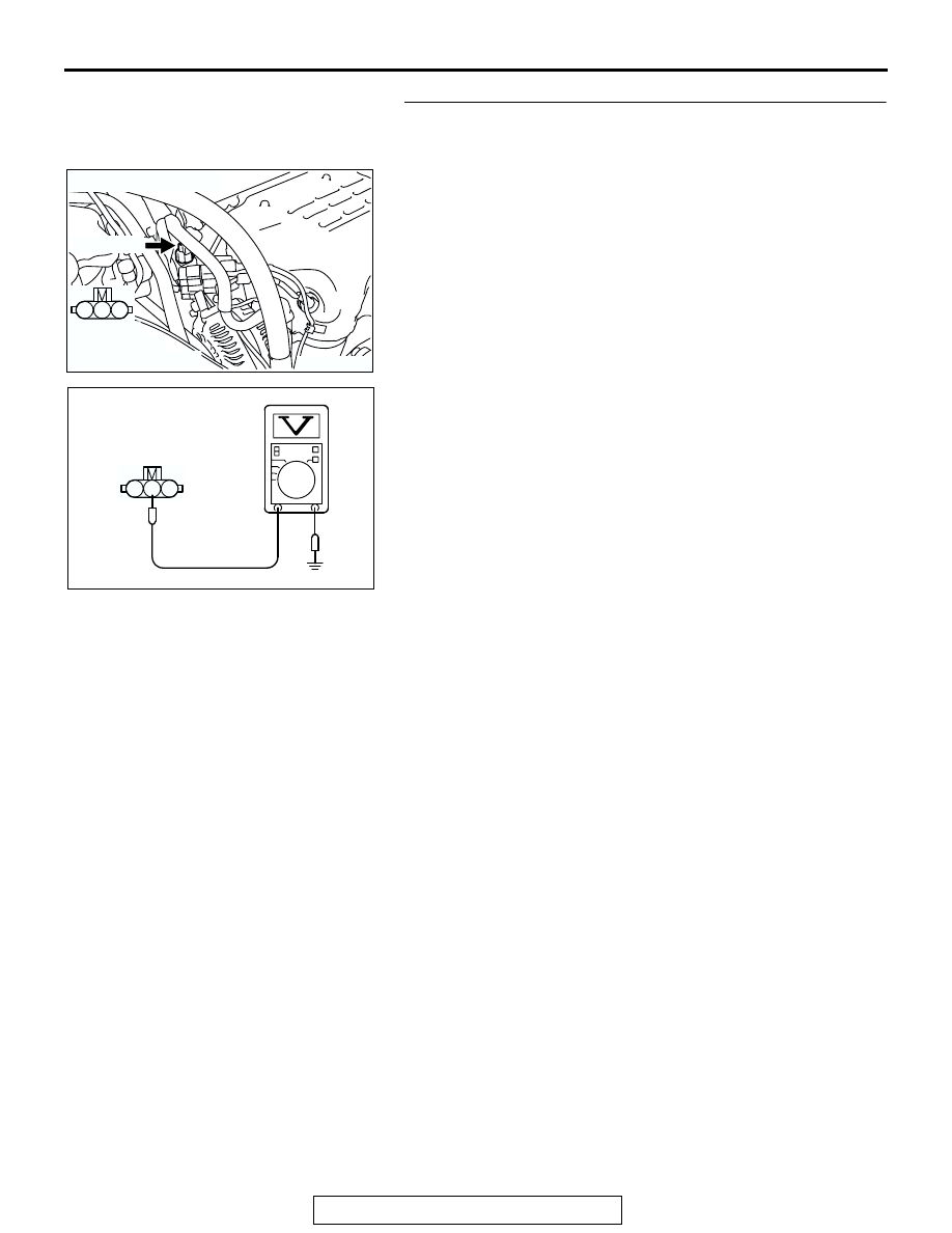
STEP 6. Measure the sensor supply voltage at crankshaft 
position sensor intermediate harness side connector 
B-119.

(1) Disconnect the connector B-119 and measure at the 

harness side.

(2) Turn the ignition switch to the "ON" position.

(3) Measure the voltage between terminal No. 2 and ground.

• Voltage should be between 4.9 and 5.1 volts.

(4) Turn the ignition switch to the "LOCK" (OFF) position.
Q: Is the measured voltage between 4.9 and 5.1 volts?

YES : Go to Step 11.
NO :  Go to Step 7.

AK303860

1

2

3

AB

CONNECTOR: B-119

B-119 (GR)

HARNESS 
CONNECTOR:
COMPONENT SIDE

1

2

3

AK302110

B-119 HARNESS
CONNECTOR:
COMPONENT SIDE

AC

MULTIPORT FUEL INJECTION (MFI) DIAGNOSIS

TSB Revision

MULTIPORT FUEL INJECTION (MFI) <2.4L ENGINE>

13A-550

STEP 7. Measure the sensor supply voltage at PCM 
connector B-22 by using power plant ECU check harness 
special tool MB991923.

(1) Disconnect the all PCM connectors and connect power 

plant ECU check harness special tool MB991923 between 
the separated connectors.

(2) Disconnect the crankshaft position sensor intermediate 

connector B-119.

(3) Turn the ignition switch to the "ON" position.

AK303016

104

96

94

95

93 92 91

99 98 97

103 102 101 100

108 107 106 105

113 112 111 110 109

CONNECTOR: B-22

B-22 (B)

PCM

AB

HARNESS CONNECTOR: 
COMPONENT SIDE

AIR CLEANER

AK202956

104

96

94

95

93 92 91

99 98 97

103 102 101 100

108 107 106 105

113 112 111 110 109

AB

POWER PLANT ECU 
CHECK HARNESS CONNECTOR

MB991923

PCM

MULTIPORT FUEL INJECTION (MFI) DIAGNOSIS

TSB Revision

MULTIPORT FUEL INJECTION (MFI) <2.4L ENGINE>

13A-551

(4) Measure the voltage between terminal No. 103 and ground.

• Voltage should be between 4.9 and 5.1 volts.

(5) Turn the ignition switch to the "LOCK" (OFF) position.
Q: Is the measured voltage between 4.9 and 5.1 volts?

YES : Go to Step 8.
NO :  Go to Step 9.

STEP 8. Check harness connector B-22 at PCM for 
damage.

Q: Is the harness connector in good condition?

YES : Repair harness wire between crankshaft position 

sensor intermediate connector B-119 (terminal No. 2) 
and PCM connector B-22 (terminal No. 103) because 
of open circuit. Then go to Step 22.

NO :  Repair or replace it. Refer to GROUP 00E, Harness 

Connector Inspection 

P.00E-2

. Then go to Step 22.

104

96

94

95

93 92 91

99 98 97

103 102 101 100

108 107 106 105

113 112 111 110 109

AK202940AB

POWER PLANT ECU 
CHECK HARNESS 
CONNECTOR 

AK303016

104

96

94

95

93 92 91

99 98 97

103 102 101 100

108 107 106 105

113 112 111 110 109

CONNECTOR: B-22

B-22 (B)

PCM

AB

HARNESS CONNECTOR: 
COMPONENT SIDE

AIR CLEANER

MULTIPORT FUEL INJECTION (MFI) DIAGNOSIS

TSB Revision

MULTIPORT FUEL INJECTION (MFI) <2.4L ENGINE>

13A-552

STEP 9. Check harness connector B-22 at PCM for 
damage.

Q: Is the harness connector in good condition?

YES : Go to Step 10.
NO :  Repair or replace it. Refer to GROUP 00E, Harness 

Connector Inspection 

P.00E-2

. Then go to Step 22.

AK303016

104

96

94

95

93 92 91

99 98 97

103 102 101 100

108 107 106 105

113 112 111 110 109

CONNECTOR: B-22

B-22 (B)

PCM

AB

HARNESS CONNECTOR: 
COMPONENT SIDE

AIR CLEANER


Content   ..  931  932  933  934   ..