Mitsubishi Galant (2004+). Manual - part 923
MULTIPORT FUEL INJECTION (MFI) DIAGNOSIS
TSB Revision
MULTIPORT FUEL INJECTION (MFI) <2.4L ENGINE>
13A-509
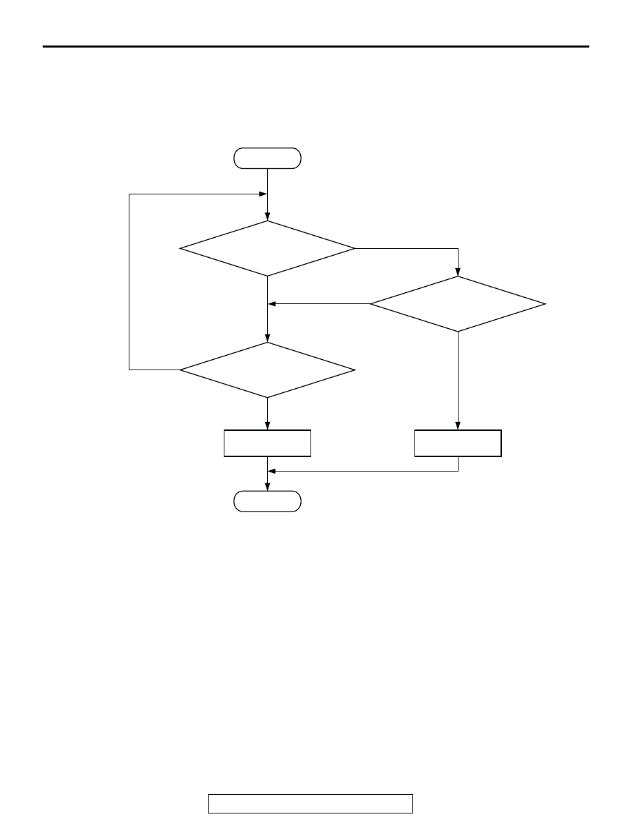
DTC SET CONDITIONS
Logic Flow Chart
Check Conditions
• Ignition switch is "ON" position.
Judgement Criteria
• Throttle position sensor (sub) output voltage
should be 4.8 volts or more for 0.5 second.
.
OBD-II DRIVE CYCLE PATTERN
None.
.
TROUBLESHOOTING HINTS (The most likely
causes for this code to be set are:)
• Throttle position sensor failed.
• Open throttle position sensor (sub) circuit, har-
ness damage, or connector damage.
• PCM failed.
START
YES
YES
YES
NO
NO
NO
CONTINUOUS
FAILURE FOR 0.5sec
MALFUNCTION
END
GOOD
OUTPUT VOLTAGE
< =2.25V
OUTPUT VOLTAGE > =4.8V
AK302032