Mitsubishi Galant (2004+). Manual - part 778


  Index      Mitsubishi     Mitsubishi Galant - service repair manual 2004 year


Search            


Content   ..  776  777  778  779   ..


Mitsubishi Galant (2004+). Manual - part 778


MANUAL A/C DIAGNOSIS

TSB Revision

HEATER, AIR CONDITIONING AND VENTILATION

55A-251

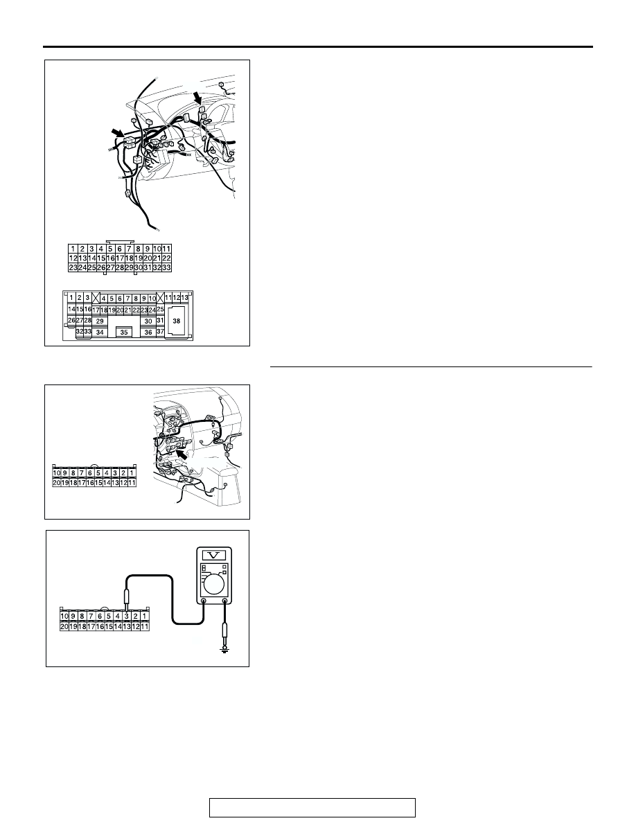
NOTE: Also check joint connector C-03 and intermediate con-
nector C-29 for loose, corroded, or damaged terminals, or ter-
minals pushed back in the connector. If joint connector C-03 or 
intermediate connector C-29 is damaged, repair or replace the 
connector as described in GROUP 00E, Harness Connector 
Inspection 

P.00E-2

.

Q: Is the wiring harness between A/C-ECU connector C-16 

(terminal 36) and the ignition switch (ACC) in good 
condition?
YES : 
It can be assumed that this malfunction is intermittent. 

Refer to GROUP 00, How to Use 
Troubleshooting/Inspection Service Points 

P.00-6

.

NO :  Repair the wiring harness. Check that the air 

conditioning works normally.

STEP 6. Measure the voltage at A/C-ECU connector C-16. 

(1) Disconnect A/C-ECU connector C-16 and measure the 

voltage at the harness side.

(2) Measure the voltage between terminal 3 and ground.

• The measured value should be approximately 12 volts 

(battery positive voltage).

Q: Is the measured voltage approx. 12 volts?

YES :  Go to Step 8.
NO :   Go to Step 7.

AC305232

CONNECTORS: C-03, C-29

C-29

C-29

C-03

C-03

AT

AC305233

CONNECTOR: C-15

BG

C-105 (B)

HARNESS SIDE

AC209365

CONNECTOR C-15 
(HARNESS SIDE)

HM

MANUAL A/C DIAGNOSIS

TSB Revision

HEATER, AIR CONDITIONING AND VENTILATION

55A-252

STEP 7. Check the wiring harness between A/C-ECU 
connector C-16 (terminal 3) and the battery.

NOTE: Also check joint connector C-01 and intermediate con-
nector C-29 for loose, corroded, or damaged terminals, or ter-
minals pushed back in the connector. If joint connector C-01 or 
intermediate connector C-29 is damaged, repair or replace the 
connector as described in GROUP 00E, Harness Connector 
Inspection 

P.00E-2

.

Q: Is the wiring harness between A/C-ECU connector C-16 

(terminal 3) and the battery in good condition?
YES : 
It can be assumed that this malfunction is intermittent. 

Refer to GROUP 00, How to Use 
Troubleshooting/Inspection Service Points 

P.00-6

.

NO :  Repair the wiring harness. Check that the air 

conditioning works normally.

AC305233

CONNECTOR: C-15

BG

C-105 (B)

HARNESS SIDE

AC305232

CONNECTORS: C-01, C-29

C-01

C-29

AS

C-01

C-29

MANUAL A/C DIAGNOSIS

TSB Revision

HEATER, AIR CONDITIONING AND VENTILATION

55A-253

STEP 8. Measure the resistance at A/C-ECU connector 
C-16.

(1) Disconnect A/C-ECU connector C-16, and measure at the 

wiring harness side.

(2) Measure the resistance between terminal 27 and ground.

• The measured value should be 2 ohms or less.

Q: Does the measured resistance value correspond with 

this range?
YES : 
Replace the A/C-ECU, and check that the air 

conditioning works normally.

NO :   Go to Step 9.

STEP 9. Check the wiring harness between A/C-ECU 
connector C-16 (terminal 27) and the ground.

Q: Is the wiring harness between A/C-ECU connector C-16 

(terminal 27) and ground in good condition?
YES : 
It can be assumed that this malfunction is intermittent. 

Refer to GROUP 00, How to Use 
Troubleshooting/Inspection Service Points 

P.00-6

check that the air conditioning works normally.

NO :  Repair the wiring harness. Check that the air 

conditioning works normally.

AC305233

HARNESS SIDE

C-16 (B)

21

22

23

24

25

26

27

28

29

30

31

32

33

34

35

36

BX

CONNECTOR: C-16

AC209364

21

22

23

24

25

26

27

28

29

30

31

32

33

34

35

36

CONNECTOR C-16 
(HARNESS SIDE)

JE

AC305233

HARNESS SIDE

C-16 (B)

21

22

23

24

25

26

27

28

29

30

31

32

33

34

35

36

BX

CONNECTOR: C-16

MANUAL A/C DIAGNOSIS

TSB Revision

HEATER, AIR CONDITIONING AND VENTILATION

55A-254

DATA LIST REFERENCE TABLE

M1554005100136

MUT-III SCAN 
TOOL DISPLAY

ITEM 
NO.

INSPECTION ITEM INSPECTION REQUIREMENT

NORMAL VALUE

Ambient air 
temperature 
sensor

02

Ambient air 
temperature sensor

Ignition switch: ON

Outside air 
temperature and 
temperature 
displayed on the 
scan tool are 
identical.

Air thermo sensor 03

Air thermo sensor

Ignition switch: ON

The temperature 
measured behind 
the evaporator 
matches the 
displayed value on 
the scan tool while 
the engine is cold.

Pressure sensor

04

A/C pressure sensor Ignition switch: ON

Measured refrigerant 
pressure is nearly 
equal to the value 
shown on the scan 
tool.

Heater water 
temperature 
sensor

05

Engine coolant 
temperature sensor 
(Data received by 
CAN 
Communication)

Ignition switch: ON

Engine coolant 
temperature and 
temperature 
displayed on the 
scan tool are 
identical.

Air mix 
potentiometer

10

Air mixing damper 
control motor 
potentiometer

Ignition switch: ON Damper 

position

Opening degree (%)

MAX. HOT

Approx. 100

MAX. COOL

Approx. 0

Air mix 
potentiometer 
(Target)

11

Target value for air 
mixing damper 
control motor 
potentiometer

Ignition switch: ON Damper 

position

Opening degree (%)

MAX. HOT

Approx. 100

MAX. COOL

Approx. 0

Air outlet c/o 
potentiometer

12

Mode selection 
damper control 
motor potentiometer

Ignition switch: ON Damper 

position

Opening degree (%)

FACE

Approx. 100

FOOT

Approx. 75

FOOT/DEF.

Approx. 50

DEF.

Approx. 0

Air outlet c/o 
potentiometer 
(target)

13

Target value for 
mode selection 
damper control 
motor potentiometer

Ignition switch: ON Damper 

position

Opening degree (%)

FACE

Approx. 100

FOOT

Approx. 75

FOOT/DEF.

Approx. 50

DEF.

Approx. 0


Content   ..  776  777  778  779   ..