Mitsubishi Galant (2004+). Manual - part 736


  Index      Mitsubishi     Mitsubishi Galant - service repair manual 2004 year


Search            


Content   ..  734  735  736  737   ..


Mitsubishi Galant (2004+). Manual - part 736


MANUAL A/C DIAGNOSIS

TSB Revision

HEATER, AIR CONDITIONING AND VENTILATION

55A-83

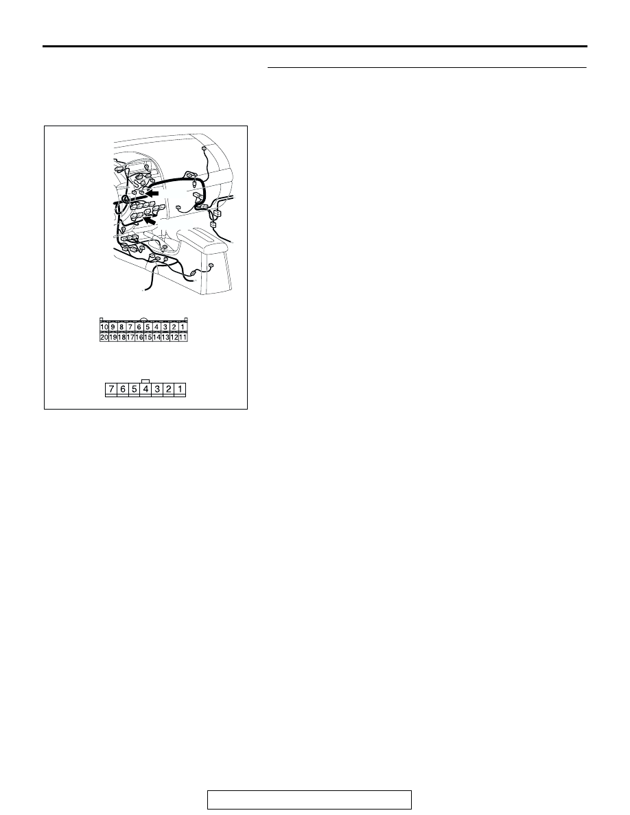
STEP 5. Check the wiring harness between A/C-ECU 
connector C-15 (terminals 1 and 2) and air mixing damper 
control motor and potentiometer connector C-105 
(terminals 1 and 2).

Q: Are the wiring harness between A/C-ECU connector 

C-15 (terminals 1 and 2) and air mixing damper control 
motor and potentiometer connector C-105 (terminals 1 
and 2) in good condition?
YES : 
Go to Step 6.
NO :  Repair the wiring harness. Then go to Step 7.

AC305234

HARNESS SIDE

C-15

AJ

CONNECTORS: C-15, C-105

C-105

HARNESS SIDE

C-105

C-15 (B)

MANUAL A/C DIAGNOSIS

TSB Revision

HEATER, AIR CONDITIONING AND VENTILATION

55A-84

STEP 6. Check the air mixing damper control motor and 
potentiometer.

CAUTION

Do not apply battery voltage when the damper is in the 
MAX COOL or MAX HOT position.
Check the air mix damper control motor by the following proce-
dures.

Q: Are the air mixing damper control motor and 

potentiometer in good condition?
YES : 
Repair the A/C-ECU. Then go to Step 7.
NO :  Replace the air mixing damper control motor and 

potentiometer. Then go to Step 7 .

LEVER POSITION BATTERY 

CONNECTION

LEVER 
OPERATION

At the MAX COOL 
position

• Connect 

terminal 2 to the 
positive battery 
terminal

• Connect 

terminal 1 to the 
negative battery 
terminal

The lever moves 
from the MAX 
COOL position to 
the MAX HOT 
position

At the MAX HOT 
position

• Connect 

terminal 1 to the 
positive battery 
terminal

• Connect 

terminal 2 to the 
negative battery 
terminal

The lever moves 
from the MAX HOT 
position to the MAX 
COOL position

AC206296

MAX HOT POSITION

MAX COOL POSITION

1 2

4

3

5

7

6

AB

MANUAL A/C DIAGNOSIS

TSB Revision

HEATER, AIR CONDITIONING AND VENTILATION

55A-85

STEP 7. Recheck for diagnostic trouble code.

Check again if the DTC is set.

1. Connect scan tool MB991958 to the data link connector
2. Turn the ignition switch to the "ON" position.
3. Check if the DTC is set.
4. Turn the ignition switch to the "LOCK" (OFF) position.

Q: Is the check result satisfactory?

YES : The procedure is complete.
NO :  Return to Step 1.

AC305412

AB

MB991910

DATA LINK

CONNECTOR

MB991824

MB991827

MANUAL A/C DIAGNOSIS

TSB Revision

HEATER, AIR CONDITIONING AND VENTILATION

55A-86

DTC B1061, B1062: Mode Selection Damper Control Motor and Potentiometer

.

DTC SET CONDITION

• DTC B1061 or B1062 is set if there is an open or 

short circuit in the potentiometer input circuit, or if 
there is an open in the power circuit or ground cir-
cuit.

.

TECHNICAL DESCRIPTION (COMMENT)

Current trouble

• The A/C-ECU, the mode selection damper con-

trol motor and potentiometer, or connector(s) or 
wiring between the two may be defective.

Past trouble

• If DTC B1061 or B1062 is stored as a past trou-

ble, carry out diagnosis with particular emphasis 
on wiring and connector(s) between the A/C-ECU 
and the mode selection damper control motor 
and potentiometer. If the connectors and wiring 
are normal, and obviously the ECU is the cause 
of the trouble, replace the ECU. If in doubt, do not 
replace the ECU.

TROUBLESHOOTING HINT

• Malfunction of connector.

• Malfunction of the harness.

• Malfunction of the mode selection damper control 

motor and potentiometer.

• Malfunction of the A/C-ECU.

MODE SELECTION
DAMPER CONTROL
MOTOR AND
POTENTIOMETER

JOINT
CONNECTOR (2)

A/C-ECU

Mode Selection Damper Control Motor Potentiometer Circuit

AC305233

C-16 (B)

C-15 (B)

CONNECTORS: C-15, C-16

BE

AC305231CG

CONNECTOR: C-03, C-102

C-03

C-102


Content   ..  734  735  736  737   ..