Mitsubishi Galant (2004+). Manual - part 733


  Index      Mitsubishi     Mitsubishi Galant - service repair manual 2004 year


Search            


Content   ..  731  732  733  734   ..


Mitsubishi Galant (2004+). Manual - part 733


MANUAL A/C DIAGNOSIS

TSB Revision

HEATER, AIR CONDITIONING AND VENTILATION

55A-71

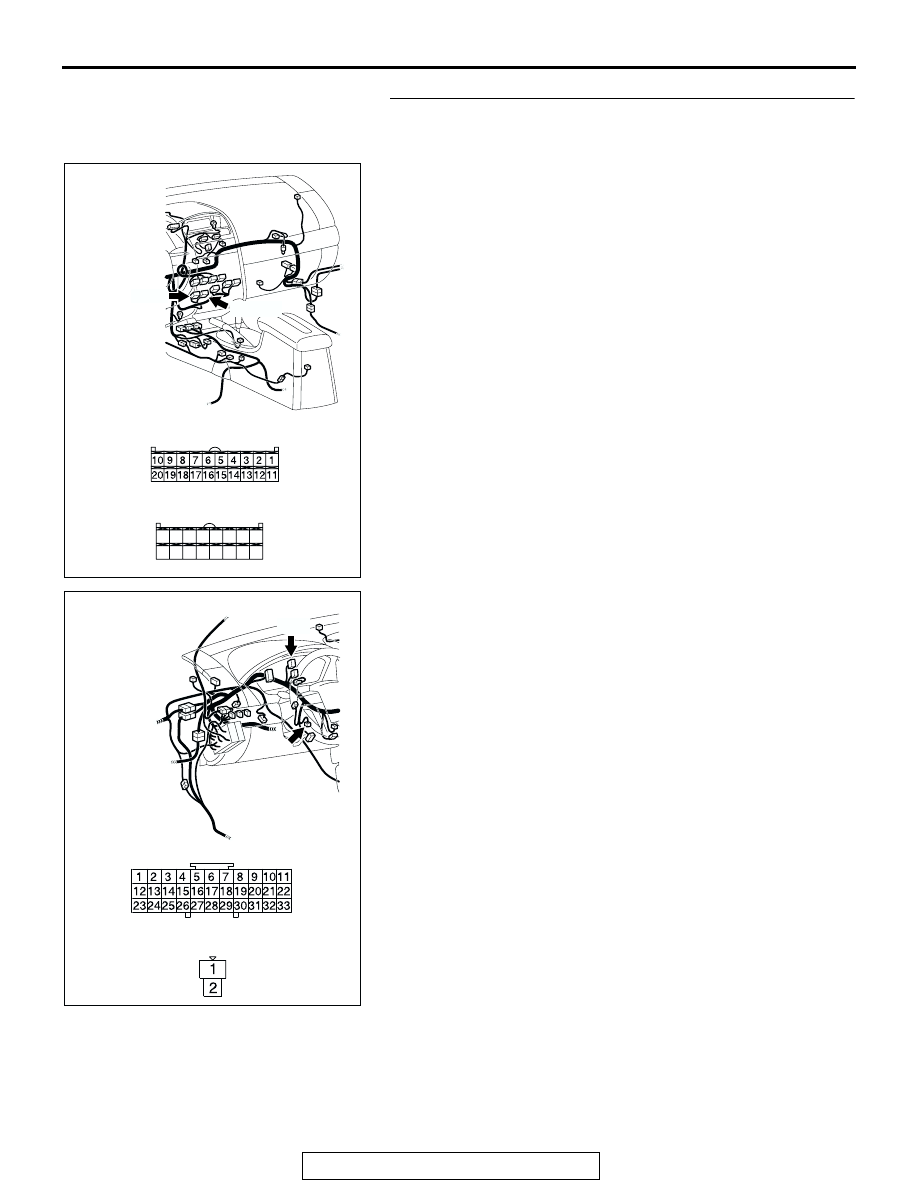
STEP 5. Check the wiring harness between A/C-ECU 
connector C-15 (terminal 20), C-16 (terminal 24) and air 
thermo sensor connector C-126 (terminals 1 and 2).

AC305234

CONNECTORS: C-15, C-16

C-16 (B)

HARNESS SIDE

C-16

C-15

C-15 (B)

HARNESS SIDE

21

22

23

24

25

26

27

28

29

30

31

32

33

34

35

36

AG

AC305232

C-03

C-126

C-03

HARNESS SIDE

C-126

AP

CONNECTORS: C-03, C-126

MANUAL A/C DIAGNOSIS

TSB Revision

HEATER, AIR CONDITIONING AND VENTILATION

55A-72

NOTE: Also check joint connector C-03 for loose, corroded, or 
damaged terminals, or terminals pushed back in the connector. 
If joint connector C-03 is damaged, repair or replace the con-
nector as described in GROUP 00E, Harness Connector 
Inspection 

P.00E-2

.

Q: Is the wiring harness between A/C-ECU connector C-15 

(terminal 20), C-16 (terminal 23) and air thermo sensor 
connector C-126 (terminals 1 and 2) in good condition?
YES : 
Go to Step 6.
NO :  Repair the wiring harness. Then go to Step 7.

STEP 6. Check the air thermo sensor.

(1) Disconnect the air thermo sensor connector C-126.

(2) Measure the resistance between connector terminals 1 and 

2 under at least two different temperatures. The resistance 

values should generally match those in the graph. 
NOTE: The temperature at the check should not exceed the 
range in the graph. 

Q: Is the air thermo sensor in good condition?

YES : Replace the A/C-ECU. Then go to Step 7.
NO :  Replace the air thermo sensor. Then go to Step 7.

AC305231

CONNECTOR: C-126

CB

HARNESS SIDE

AC001043

RESISTANCE k

8

6

4

2

0

-10

0

 10

 20

 30

   40

TEMPERATURE ˚C(˚F)

AB

(14)

(32)

(50)

(86)

(104)

(68)

MANUAL A/C DIAGNOSIS

TSB Revision

HEATER, AIR CONDITIONING AND VENTILATION

55A-73

STEP 7. Recheck for diagnostic trouble code.

Check again if the DTC is set.

1. Connect scan tool MB991958 to the data link connector
2. Turn the ignition switch to the "ON" position.
3. Check if the DTC is set.
4. Turn the ignition switch to the "LOCK" (OFF) position.

Q: Is the check result satisfactory?

YES : The procedure is complete.
NO :  Return to Step 1.

AC305412

AB

MB991910

DATA LINK

CONNECTOR

MB991824

MB991827

MANUAL A/C DIAGNOSIS

TSB Revision

HEATER, AIR CONDITIONING AND VENTILATION

55A-74

DTC B1041, B1042: Air Mixing Damper Control Motor and Potentiometer (Potentiometer system)

.

DTC SET CONDITION

• DTC B1041 or B1042 is set if there is an open or 

short circuit in the potentiometer input circuit, or if 
there is an open circuit in the power circuit or 
earth circuit.

.

TECHNICAL DESCRIPTION (COMMENT)

Current trouble

• The A/C-ECU, the air mixing damper control 

motor and potentiometer, or connector(s) or wir-
ing between the two may be defective.

Past trouble

• If DTC B1041 or B1042 is stored as a past trou-

ble, carry out diagnosis with particular emphasis 
on wiring and connector(s) between the A/C-ECU 
and the air mixing damper control motor and 
potentiometer. If the connectors and wiring are 
normal, and obviously the ECU is the cause of 
the trouble, replace the ECU. If in doubt, do not 
replace the ECU.

TROUBLESHOOTING HINT

• Malfunction of connector.

• Malfunction of the harness.

• Malfunction of the air mixing damper control 

motor and potentiometer.

• Malfunction of the A/C-ECU.

AIR MIXING
DAMPER CONTROL
MOTOR AND
POTENTIOMETER

JOINT
CONNECTOR (2)

A/C-ECU

Air Mixing Damper Control Motor Potentiometer Circuit

AC305231AZ

CONNECTOR: C-03

AC305233

C-16 (B)

C-15 (B)

BF

C-105

CONNECTORS: C-15, C-16, C-105


Content   ..  731  732  733  734   ..