Mitsubishi Galant (2004+). Manual - part 721


  Index      Mitsubishi     Mitsubishi Galant - service repair manual 2004 year


Search            


Content   ..  719  720  721  722   ..


Mitsubishi Galant (2004+). Manual - part 721


MANUAL A/C DIAGNOSIS

TSB Revision

HEATER, AIR CONDITIONING AND VENTILATION

55A-23

DTC B1041, B1042: Air Mixing Damper Control Motor and Potentiometer (Potentiometer system)

.

DTC SET CONDITION

• DTC B1041 or B1042 is set if there is an open or 

short circuit in the potentiometer input circuit, or if 
there is an open circuit in the power circuit or 
earth circuit.

.

TECHNICAL DESCRIPTION (COMMENT)

Current trouble

• The A/C-ECU, the air mixing damper control 

motor and potentiometer, or connector(s) or wir-
ing between the two may be defective.

Past trouble

• If DTC B1041 or B1042 is stored as a past trou-

ble, carry out diagnosis with particular emphasis 
on wiring and connector(s) between the A/C-ECU 
and the air mixing damper control motor and 
potentiometer. If the connectors and wiring are 
normal, and obviously the ECU is the cause of 
the trouble, replace the ECU. If in doubt, do not 
replace the ECU.

TROUBLESHOOTING HINT

• Malfunction of connector.

• Malfunction of the harness.

• Malfunction of the air mixing damper control 

motor and potentiometer.

• Malfunction of the A/C-ECU.
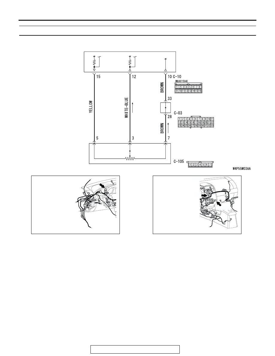
AIR MIXING
DAMPER CONTROL
MOTOR AND
POTENTIOMETER

JOINT
CONNECTOR (2)

A/C-ECU

Air Mixing Damper Control Motor Potentiometer

AC305231AZ

CONNECTOR: C-03

AC305233

CONNECTOR: C-10, C-105

AZ

C-105

C-10 (B)

MANUAL A/C DIAGNOSIS

TSB Revision

HEATER, AIR CONDITIONING AND VENTILATION

55A-24

DIAGNOSIS

Required Special Tool:

•  MB991958: Scan Tool (MUT-III Sub Assembly)

• MB991824: Vehicle Communication Interface (V.C.I.)

• MB991827: MUT-III USB Cable

• MB991910: MUT-III Main Harness A (Vehicles with CAN 

communication system)

STEP 1. Using scan tool MB991958, diagnose the CAN bus 
line.

Use scan tool MB991958 to diagnose the CAN bus lines.
(1) Connect scan tool MB991958 to the data link connector.
(2) Turn the ignition switch to "ON" position.

(3) Diagnose the CAN bus line.
Q: Is the check result satisfactory?

YES : Go to Step 2.
NO :  Repair the CAN bus lines. (Refer to GROUP 54C, 

Diagnosis-Can Bus Diagnostic Chart 

P.54C-621

). 

Then go to Step 7.

STEP 2. Recheck for diagnostic trouble code.

Recheck if the DTC is set.

1. Erase the DTC.
2. Turn the ignition switch to "ON" position.
3. Check if the DTC is set.

Q: Is the check result satisfactory?

YES : It can be assumed that this malfunction is intermittent. 

Refer to GROUP 00, How to Use 
Troubleshooting/Inspection Service Points 

− How to 

Use Troubleshooting/Inspection Service Points 

P.00-6

.

NO :  Go to Step 3. 

AC305412

AB

MB991910

DATA LINK

CONNECTOR

MB991824

MB991827

MANUAL A/C DIAGNOSIS

TSB Revision

HEATER, AIR CONDITIONING AND VENTILATION

55A-25

STEP 3. Using scan tool MB991958, check data list item 10: 
air mix potentiometer.

CAUTION

To prevent damage to scan tool MB991958, always turn the 
ignition switch to the "LOCK" (OFF) position before con-
necting or disconnecting scan tool MB991958.
(1) Connect scan tool MB991958 to the data link connector.
(2) Start the engine.
(3) Set scan tool MB991958 to the data reading mode for item 

10: air mix potentiometer.

• Check that the set position of the heater control matches 

the displayed position on the scan tool.

(4) Turn the ignition switch to the "LOCK" (OFF) position.
Q: Is the sensor within the specified range?

YES : Replace the A/C-ECU. Then go to Step 7.
NO :  Go to Step 4.

STEP 4. Check A/C-ECU connector C-10 and air mixing 
damper control motor and potentiometer connector C-105 
for loose, corroded or damaged terminals, or terminals 
pushed back in the connector.

Q: Are A/C-ECU connector C-10 and air mixing damper 

control motor and potentiometer connector C-105 in 
good condition?
YES : 
Go to Step 5.
NO :  Repair or replace the connector. Refer to GROUP 

00E, Harness Connector Inspection 

P.00E-2

. Then g

to Step 7.

AC305412

AB

MB991910

DATA LINK

CONNECTOR

MB991824

MB991827

AC305234

CONNECTORS: C-10, C-105

C-10 (B)

C-105

HARNESS SIDE

C-10

C-105

HARNESS SIDE

AE

MANUAL A/C DIAGNOSIS

TSB Revision

HEATER, AIR CONDITIONING AND VENTILATION

55A-26

STEP 5. Check the wiring harness between A/C-ECU 
connectors C-10 (terminals 15, 12 and 10) and air mixing 
damper control motor and potentiometer connector C-105 
(terminals 5, 3 and 7).

NOTE: Also check joint connector C-03 for loose, corroded, or 
damaged terminals, or terminals pushed back in the connector. 
If joint connector C-03 is damaged, repair or replace the con-
nector as described in GROUP 00E, Harness Connector 
Inspection 

P.00E-2

.

Q: Are the wiring harness between A/C-ECU connector 

C-10 (terminals 15, 12 and 10) and air mixing damper 
control motor and potentiometer connector C-105 
(terminals 5, 3 and 7) in good condition?
YES : 
Go to Step 6.
NO :  Repair the wiring harness. Then go to Step 7.

AC305234

CONNECTORS: C-10, C-105

C-10 (B)

C-105

HARNESS SIDE

C-10

C-105

HARNESS SIDE

AE

AC305231BP

CONNECTOR: C-03


Content   ..  719  720  721  722   ..