Mitsubishi Galant (2004+). Manual - part 712


  Index      Mitsubishi     Mitsubishi Galant - service repair manual 2004 year


Search            


Content   ..  710  711  712  713   ..


Mitsubishi Galant (2004+). Manual - part 712


TRANSAXLE ASSEMBLY

TSB Revision

AUTOMATIC TRANSAXLE

23A-399

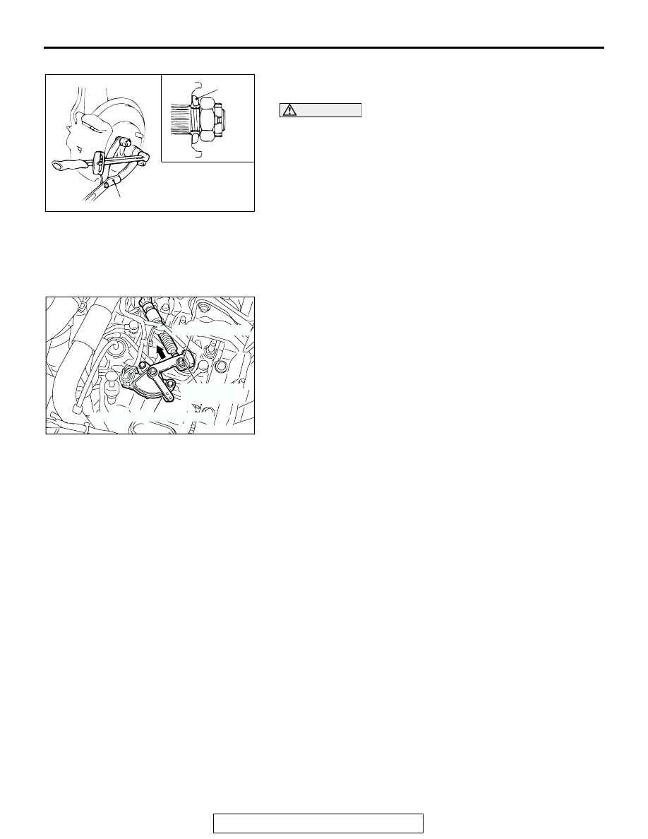
>>D<< DRIVE SHAFT NUT INSTALLATION
1. Be sure to install the drive shaft washer in the specified 

direction.

CAUTION

Before securely tightening the drive shaft nuts, make sure 
there is no load on the wheel bearings. Otherwise the 
wheel bearing will be damaged.
2. Using special tool MB990767, tighten the drive shaft nut to 

the specified torque.

Tightening torque: 226 

± 29 Nm (167 ± 21 ft-lb)

.

>>E<< ADJUSTING NUT/TRANSAXLE CONTROL CABLE 
(TRANSAXLE SIDE) INSTALLATION
1. Place the selector lever and manual control lever in the “N” 

position.

2. Place the cable stud into the manual control lever slot and 

install the nut loosely. Gently push the transaxle control 
cable into the manual control lever slot until the cable is taut. 
Tighten the nut to the specified torque.

Tightening torque: 12 

± 2 Nm (107 ± 17 in-lb)

AC210244AB

MB990767

WASHER

AC305532

12 ± 2 N·m
107 ± 17 in-lb

MANUAL CONTROL LEVER

ADJUSTING NUT

AE

TRANSAXLE ASSEMBLY

TSB Revision

AUTOMATIC TRANSAXLE

23A-400

REMOVAL AND INSTALLATION

M1231005700459

<F4A5A>

CAUTION

*

: Indicates parts which should be temporarily tightened, and then fully tightened after placing the 

vehicle horizontally and loading the full weight of the engine on the vehicle body.

Pre-installation Operation
• Front Under Cover, Side Under Cover Removal
• Transmission Fluid Draining (Refer to GROUP 00, Main-

tenance Service 

− Automatic Transaxle 

P.00-50

.)

• Engine Cover Removal (Refer to GROUP 11C, Engine 

Assembly 

P.11C-15

.)

• Air Cleaner Assembly Removal (Refer to GROUP 15, Air 

Cleaner 

P.15-4

.)

• Powertrain Control Module (PCM) Removal (Refer to 

GROUP 13A 

P.13A-1121

.)

• Battery and Battery Tray Removal
• Front Exhaust Pipe Removal (Refer to GROUP 15, 

Exhaust Pipe and Main Muffler 

P.15-21

.)

Post-installation Operation
• Front Exhaust Pipe Installation (Refer to GROUP 15, 

Exhaust Pipe and Main Muffle

P.15-21

.)

• Battery and Battery Tray Installation
• Powertrain Control Module (PCM) Installation (Refer to 

GROUP 13A 

P.13A-1121

.)

• Air Cleaner Assembly Installation (Refer to GROUP 15, 

Air Cleaner 

P.15-4

.)

• Engine Cover Installation (Refer to GROUP 11C, Engine 

Assembly 

P.11C-15

.)

• Transmission Fluid Supplying (Refer to GROUP 00, Main-

tenance Service 

− Automatic Transaxle 

P.00-50

.)

• Front Under Cover, Side Under Cover Installation

• Selector Lever Operation Check (Refer to 

P.23A-381

.)

• Speedometer Operation Check (Refer to GROUP 54A, 

Combination Meter 

− On-vehicle Service − Speedometer 

Check 

P.54A-106

.)

• Front Wheel Alignment Check and Adjustment (Refer to 

GROUP 33, On-vehicle Service 

− Front Wheel Alignment 

Check and Adjustment 

P.33-6

.)

AC305969

7

N

8

226 ± 29 N·m
167 ± 21 ft-lb

65 ± 6 N·m
48 ± 4 ft-lb

12

N

48 ± 7 N·m
36 ± 5 ft-lb

10

9

48 ± 7 N·m
36 ± 5 ft-lb

N

14

16

19

2

1

12 ± 2 N·m
107 ± 17 in-lb

73 ± 10 N·m
54 ± 7 ft-lb

3

4

5

6

22

30 ± 3 N·m
23 ± 2 ft-lb

30 ± 3 N·m
22 ± 2 ft-lb

41 ± 4 N·m
30 ± 3 ft-lb

N

17

19

AB

23

23

73 ± 10 N·m
54 ± 7 ft-lb

13

15

18

21

21

11

REMOVAL STEPS

>>E<<

1.

ADJUSTING NUT

>>E<<

2.

TRANSAXLE CONTROL CABLE 
CONNECTION

3.

INHIBITOR SWITCH SENSOR 
CONNECTOR

REMOVAL STEPS (Continued)

TRANSAXLE ASSEMBLY

TSB Revision

AUTOMATIC TRANSAXLE

23A-401

4.

A/T CONTROL SOLENOID VALVE 
ASSEMBLY CONNECTOR

5.

INPUT SHAFT SPEED SENSOR 
CONNECTOR

6.

OUTPUT SHAFT SPEED 
SENSOR CONNECTOR

7.

SPLIT PIN

<<A>>

>>D<<

8.

DRIVE SHAFT NUT

9.

WHEEL SPEED SENSOR 

10. WHEEL SPEED SENSOR 

BRACKET

11. BRAKE HOSE CLAMP
12. STABILIZER LINK CONNECTION 

<STRUT SIDE>

13. SELF-LOCKING NUT 

(CONNECTION FOR TIE ROD 
END)

<<B>>

14. TIE ROD END CONNECTION
15. SELF-LOCKING NUT 

(CONNECTION FOR LOWER 
ARM BALL JOINT)

<<B>>

16. LOWER ARM BALL JOINT 

CONNECTION

<<C>>

>>C<<

17. DRIVE SHAFT <LH>
18. CIRCLIP

<<C>>

>>C<<

19. DRIVE SHAFT AND INNER 

SHAFT ASSEMBLY <RH>

20. TRANSMISSION FLUID COOLER 

HOSE

21. STARTER MOTOR INSTALLATION 

BOLTS

22. STARTER MOTOR
23. TRANSAXLE ASSEMBLY UPPER 

PART COUPLING BOLTS

REMOVAL STEPS (Continued)

TRANSAXLE ASSEMBLY

TSB Revision

AUTOMATIC TRANSAXLE

23A-402

Required Special Tools:

• MB990767: End Yoke Holder

• MB991897: Ball Joint Remover

• MB990242: Puller Shaft Puller

• MB990244: Puller Bar

• MB991354: Puller Body

• MB990998: Front Hub Remover and Installer 

• MB991000: Spacer

• MB991454: Engine Hanger Balancer

• MB991895: Engine Hanger

• MB991928: Engine Hanger

• MB991932: Foot (standard)

• MB991929: Joint (50)

• MB991931: Joint (140)

AC305970

83 ± 12 N·m
61 ± 9 ft-lb

83 ± 12 N·m
61 ± 9 ft-lb

58 ± 7 N·m*
43 ± 5 ft-lb*

26

90 ± 10 N·m
67 ± 7 ft-lb

58 ± 7 N·m*
43 ± 5 ft-lb*

11 ± 0.5 N·m
93 ± 4 in-lb

49 ± 3 N·m
36 ± 2 ft-lb

25

24

32

88 ± 10 N·m
65 ± 7 ft-lb

58 ± 7 N·m*
43 ± 5 ft-lb*

83 ± 12 N·m*
61 ± 9 ft-lb*

30

30

31

29

28

33

AB

27

35 ± 6 N·m
26 ± 4 ft-lb

REMOVAL STEPS

24. COVER

<<D>>

25. TORQUE CONVERTER AND 

DRIVE PLATE BOLTS

26. CENTERMEMBER ASSEMBLY
27. ENGINE OIL PAN AND 

TRANSAXLE  COUPLING BOLTS

28. REAR ROLL STOPPER BRACKET

AIR CLEANER BRACKET

29. TRANSAXLE MOUNT BRACKET 

ASSEMBLY

>>B<<

30. TRANSAXLE MOUNT STOPPER
31. TRANSAXLE MOUNT BRACKET

<<E>>

ENGINE ASSEMBLY SUPPORT

LIFTING UP OF THE VEHICLE

SUPPORT THE TRANSAXLE 
WITH A TRANSAXLE JACK

32. TRANSAXLE ASSEMBLY LOWER 

PART COUPLING BOLTS

>>A<<

33. TRANSAXLE ASSEMBLY

REMOVAL STEPS (Continued)


Content   ..  710  711  712  713   ..