Mitsubishi Galant (2004+). Manual - part 692


  Index      Mitsubishi     Mitsubishi Galant - service repair manual 2004 year


Search            


Content   ..  690  691  692  693   ..


Mitsubishi Galant (2004+). Manual - part 692


AUTOMATIC TRANSAXLE DIAGNOSIS

TSB Revision

AUTOMATIC TRANSAXLE

23A-319

.

CIRCUIT OPERATION
If the select switch of the shift switch assembly is set 
to the sport mode, battery positive voltage will be 
applied to the PCM (terminal 39). If the shift switch of 
the shift switch assembly is set to "UP" or "DOWN" 
position, battery positive voltage will be applied to the 
PCM (terminal 32, 36).

.

COMMENT
When sport mode shift does not operate the cause is 
probably a malfunction of the transmission range 
switch circuit, shift switch assembly circuit or a defec-
tive PCM.

.

TROUBLESHOOTING HINTS (The most likely 
causes for this case:)

• Malfunction of the transmission range switch

• Malfunction of the shift switch assembly select 

switch

• Malfunction of the shift switch assembly shift 

switch (Up)

• Malfunction of the shift switch assembly shift 

switch (Down)

• Damaged harness or connector

• Malfunction of the PCM

DIAGNOSIS

Required Special Tool:

• MB991958: Scan Tool (MUT-III Sub Assembly)

• MB991824: V.C.I.

• MB991827: MUT-III USB Cable

• MB991910: MUT-III Main Harness A
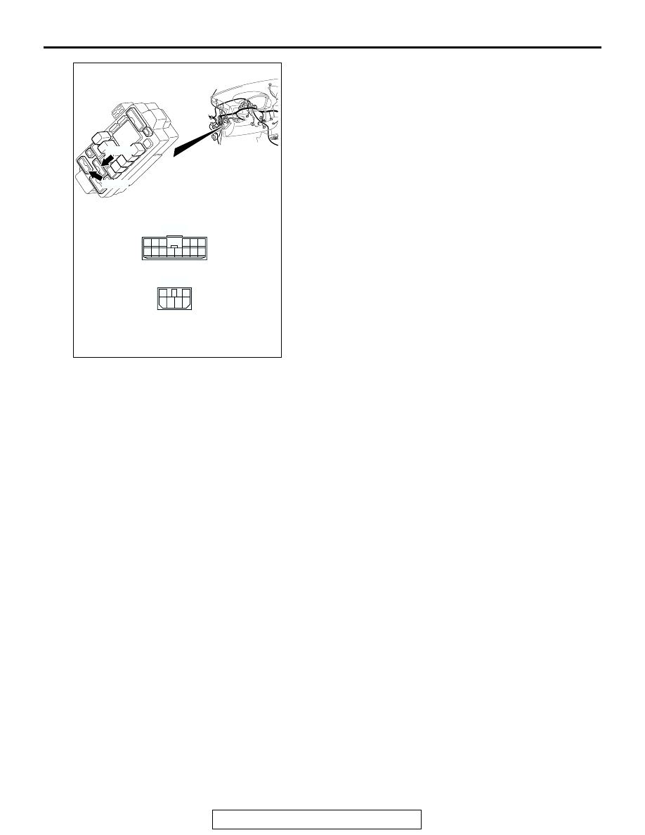
AC207134

C-214

C-215

CONNECTORS: C-214, 215

AO

1

3 4

2

6

5

C-214

C-215

6

1

7

2

9

8

10

3

5

12

11

4

1314

AUTOMATIC TRANSAXLE DIAGNOSIS

TSB Revision

AUTOMATIC TRANSAXLE

23A-320

STEP 1. Using scan tool MB991958, read the A/T 
diagnostic trouble code.

CAUTION

To prevent damage to scan tool MB991958, always turn the 
ignition switch to the "LOCK" (OFF) position before con-
necting or disconnecting scan tool MB991958.
(1) Connect scan tool MB991958 to the data link connector.
(2) Turn the ignition switch to the "ON" position.
(3) Check for A/T diagnostic trouble code.
(4) Turn the ignition switch to the "LOCK" (OFF) position.
Q: Is DTC 27 or 28 set?

YES <DTC 27 set> : Refer to 

P.23A-121

, DTC 27: 

Transmission Range Switch System (Open Circuit).

YES <DTC 28 set> : Refer to 

P.23A-166

, DTC 28: 

Transmission Range Switch System (Short Circuit).

NO :  Go to Step 2.

AC305412

AB

MB991910

DATA LINK

CONNECTOR

MB991824

MB991827

AUTOMATIC TRANSAXLE DIAGNOSIS

TSB Revision

AUTOMATIC TRANSAXLE

23A-321

STEP 2. Using scan tool MB991958, check data list item 67: 
Select Switch, item 68: Shift Switch (Up), item 69: Shift 
Switch (Down).

(1) Connect scan tool MB991958 to the data link connector.
(2) Turn the ignition switch to the "ON" position.
(3) Set scan tool MB991958 to the data reading mode for 

following items.

a. Item 67: Select Switch
b. Item 68: Shift Switch (Up)

c. Item 69: Shift Switch (Down)

NOTE: The switches above are displayed, depending on 
the selector lever condition as shown in the table.

(4) Turn the ignition switch to the "LOCK" (OFF) position.
Q: Is the switch operating properly?

YES : It can be assumed that this malfunction is intermittent. 

Refer to GROUP 00, How to Use 
Troubleshooting/Inspection Service Points 

− How to 

Cope with Intermittent Malfunction 

P.00-6

.

NO <If completely NG> : Go to Step 3.
NO <If item 68 and item 69 both are NG> : Go to Step 5. 
NO <If only item 67 is NG> : Go to Step 9.
NO <If only item 68 is NG> : Go to Step 17. 
NO <If only item 69 is NG> : Go to Step 22. 

SELECTOR LEVER 
OPERATION

DATA LIST ITEM

67

68

69

D range

OFF

OFF

OFF

Sport mode

ON

OFF

OFF

Upshift and hold the selector 
lever

ON

ON

OFF

Downshift and hold the 
selector lever

ON

OFF

ON

AC305412

AB

MB991910

DATA LINK

CONNECTOR

MB991824

MB991827

AUTOMATIC TRANSAXLE DIAGNOSIS

TSB Revision

AUTOMATIC TRANSAXLE

23A-322

STEP 3. Check PCM connector B-20 and shift switch 
assembly connector C-20 for loose, corroded or damaged 
terminals, or terminals pushed back in the connector.

Q: Are the connectors in good condition?

YES : Go to Step 4.
NO :  Repair or replace the damaged components. Refer to 

GROUP 00E, Harness Connector Inspection 

P.00E-2

.

AC306248AH

CONNECTOR: B-20

PCM

AIR
CLEANER

JAE

41

37

32

40

39

23

21 22

35

31

30

26

36

27

43

42

25

24

38

34

29

33

28

B-20

AC306349AB

CONNECTOR: C-20

4

3

1

5 6

2


Content   ..  690  691  692  693   ..