Mitsubishi Galant (2004+). Manual - part 641


  Index      Mitsubishi     Mitsubishi Galant - service repair manual 2004 year


Search            


Content   ..  639  640  641  642   ..


Mitsubishi Galant (2004+). Manual - part 641


AUTOMATIC TRANSAXLE DIAGNOSIS

TSB Revision

AUTOMATIC TRANSAXLE

23A-115

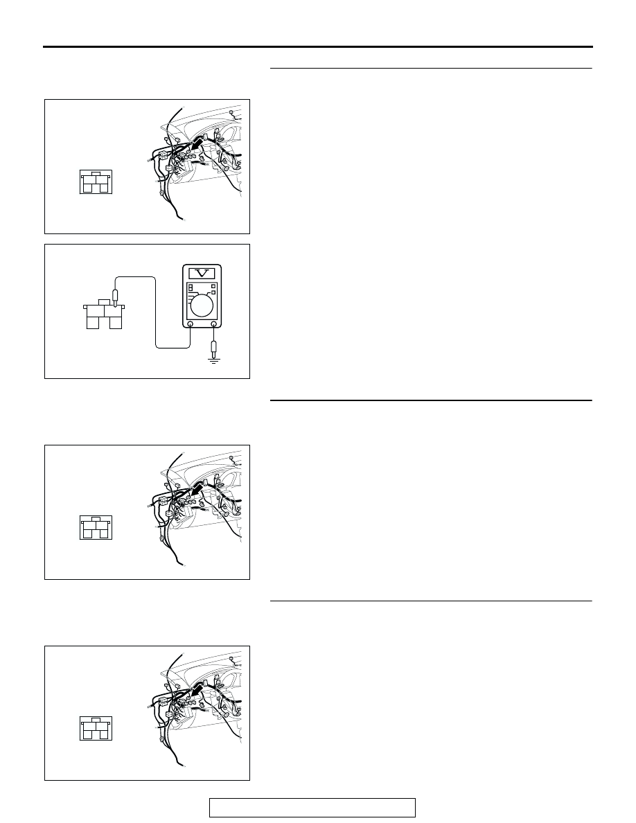
STEP 4. Measure the stoplight switch power supply 
voltage at connector C-30 by backprobing.

(1) Remove the stoplight switch from the mounting bracket.
(2) Do not disconnect connector C-30.

(3) Measure the voltage between terminal 2 and ground by 

backprobing.

• The voltage should measure battery positive voltage.

Q: Is the measured voltage battery positive voltage?

YES : Go to Step 7.
NO :   Go to step 5.

STEP 5. Check stoplight switch connector C-30 for loose, 
corroded or damaged terminals, or terminals pushed back 
in the connector.

Q: Are the connector and terminals in good condition?

YES : Go to Step 6.
NO :  Repair or replace the damaged components. Refer to 

GROUP 00E, Harness Connector Inspection 

P.00E-2

.

STEP 6. Check the harness for damage between stoplight 
switch connector C-30 terminal 2 and the power supply 
fuse.

Q: Is the harness wire in good condition?

YES : Go to Step 7.
NO :  Repair or replace the harness wire.

AC305231

CONNECTOR: C-30

AU

2

1

3

4

2

1

3

4

AC201487

C-30 HARNESS
CONNECTOR:
HARNESS SIDE

AG

AC305231

CONNECTOR: C-30

AU

2

1

3

4

AC305231

CONNECTOR: C-30

AU

2

1

3

4

AUTOMATIC TRANSAXLE DIAGNOSIS

TSB Revision

AUTOMATIC TRANSAXLE

23A-116

STEP 7. Measure the stoplight switch output voltage to the 
PCM at connector C-30 by backprobing.

(1) Remove the stoplight switch from the mounting bracket.
(2) Do not disconnect connector C-30.

(3) Measure the voltage between terminal 1 and ground by 

backprobing.

• When the switch button is out (closed circuit), voltage 

should equal battery positive voltage.

• When the switch button is depressed (open circuit), volt-

age should measure less than 1.0 volt.

Q: Is the measured voltage battery positive voltage with 

the switch button released (closed circuit), and less 
than 1.0 volt with the switch button depressed (open 
circuit)?
YES : 
Go to Step 9.
NO :  Go to Step 8.

STEP 8. Check the stoplight switch.

Refer to GROUP 35A, On-vehicle Service 

− Stoplight Switch 

Check 

P.35A-25

.

Q: Does the stoplight switch pass the checks?

YES : Go to Step 9.
NO :  Replace the stoplight switch. Refer to GROUP 35A, 

Brake Pedal 

P.35A-24

.

AC305231

CONNECTOR: C-30

AU

2

1

3

4

3

2

1

4

AC201041

C-30 HARNESS
CONNECTOR:
HARNESS SIDE

AH

ACX02208

BRAKE PEDAL

STOPLIGHT
SWITCH

AD

AUTOMATIC TRANSAXLE DIAGNOSIS

TSB Revision

AUTOMATIC TRANSAXLE

23A-117

STEP 9. Measure the stoplight switch output voltage at the 
PCM connector B-19 by using check harness special tool 
MB991923.

(1) Install the stoplight switch into the mounting bracket if it was 

removed.

(2) Disconnect all the connectors from the PCM.

(3) Connect special tool MB991923 (check harness) between 

the PCM and the body-side harness connector.

AC306248AF

B-19 
(B)

CONNECTOR: B-19

PCM

AIR
CLEANER

JAE

17

13

10

12

1516

5 6

9

2

14

18

11

4

7

3

8

1

AC209793AI

PCM

MB991923

BODY SIDE
HARNESS

SPECIAL TOOL 18-PIN CONNECTOR
(PCM CONNECTOR B-19)

B-19 (B)

4 3 2 1

7 6 5

8 9

11 10

14 13 12

18 17 16 15

AUTOMATIC TRANSAXLE DIAGNOSIS

TSB Revision

AUTOMATIC TRANSAXLE

23A-118

(4) Measure the voltage between terminal 9 and ground.

• When the brake pedal is depressed, voltage should 

measure battery positive voltage.

• When the brake pedal is not depressed, voltage should 

measure less than 1.0 volt.

Q: Is the measured voltage battery positive voltage with 

the brake pedal depressed (closed circuit), and less 
than 1.0 volt with the brake pedal released (open 
circuit)?
YES : 
Go to Step 12.
NO :  Go to Step 10.

STEP10. Check PCM connector B-19 and joint connector 
(1) C-01 for loose, corroded or damaged terminals, or 
terminals pushed back in the connector.

Q: Are the connectors and terminals in good condition?

YES : Go to Step 11.
NO :  Repair or replace the damaged components. Refer to 

GROUP 00E, Harness Connector Inspection 

P.00E-2

.

AC210383

3

17

10

13

18

4

11

14

7

1615

1

2

5

12

9

6

8

JAE

B-19 HARNESS
CONNECTOR:
COMPONENT SIDE

AC

AC306248AF

B-19 
(B)

CONNECTOR: B-19

PCM

AIR
CLEANER

JAE

17

13

10

12

1516

5 6

9

2

14

18

11

4

7

3

8

1

AC305231

CONNECTOR: C-01

AS

33

22

11

28

17

16

15

14

13

12

25

2324

2627

3

1 2

4 5

21

20

19

18

29 30

32

31

7

6

8

10

9


Content   ..  639  640  641  642   ..