Mitsubishi Galant (2004+). Manual - part 634


  Index      Mitsubishi     Mitsubishi Galant - service repair manual 2004 year


Search            


Content   ..  632  633  634  635   ..


Mitsubishi Galant (2004+). Manual - part 634


AUTOMATIC TRANSAXLE DIAGNOSIS

TSB Revision

AUTOMATIC TRANSAXLE

23A-87

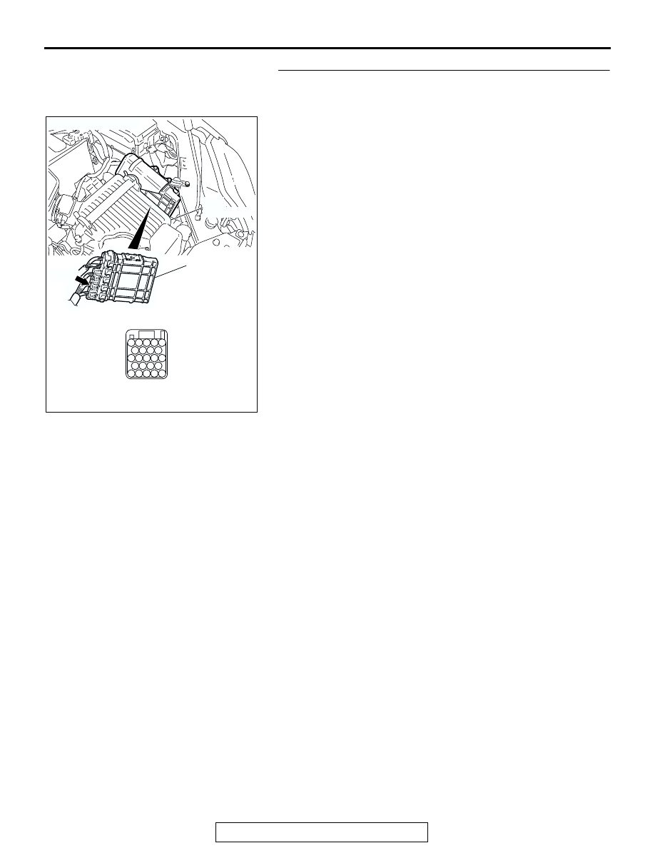
STEP 15. Check PCM connector B-22 for loose, corroded 
or damaged terminals, or terminals pushed back in the 
connector.

Q: Are the connector and terminals in good condition?

YES : Replace the PCM.
NO :  Repair or replace the damaged components. Refer to 

GROUP 00E, Harness Connector Inspection 

P.00E-2

.

AC306248AE

B-22 
(B)

CONNECTOR: B-22

PCM

AIR
CLEANER

JAE

94

98

107

103

112

91

100

109

101102

106

110

105

111

97

92

96

93

104

113

108

95

99

AUTOMATIC TRANSAXLE DIAGNOSIS

TSB Revision

AUTOMATIC TRANSAXLE

23A-88

STEP 16. Using the oscilloscope, check the input shaft 
speed sensor waveform at PCM connectors B-22 by using 
check harness special tool MB991923.

(1) Disconnect all the connectors from the PCM.

(2) Connect special tool MB991923 (check harness) between 

the PCM and the body-side harness connector.

AC306248AE

B-22 
(B)

CONNECTOR: B-22

PCM

AIR
CLEANER

JAE

94

98

107

103

112

91

100

109

101102

106

110

105

111

97

92

96

93

104

113

108

95

99

AC209793AH

SPECIAL TOOL 23-PIN CONNECTOR
WITH RED TAPE
(PCM CONNECTOR B-22)

104

96

94

95

93 92 91

99 98 97

103 102 101 100

108 107 106 105

113 112 111 110 109

PCM

MB991923

BODY SIDE
HARNESS

B-22
(GR)

AUTOMATIC TRANSAXLE DIAGNOSIS

TSB Revision

AUTOMATIC TRANSAXLE

23A-89

(3) Connect an oscilloscope probe to PCM connector B-22 

terminal 111 and to 113.

(4) Start the engine and drive the vehicle at constant speed of 

50 km/h (31 mph) (Gear range: 3rd gear).

(5) Check the input shaft speed sensor waveform.

• The input shaft speed sensor waveform should show a 

pattern similar to the illustration. The maximum value 
should be 4.8 volts or more and the minimum value 0.8 
volt or less. The output waveform should not contain 
electrical noise.

(6) Turn the ignition switch to the "LOCK" (OFF) position.
Q: Is the waveform normal?

YES : Go to Step 19.
NO :  Go to Step 17.

STEP 17. Replace the input shaft speed sensor.

(1) Replace the input shaft speed sensor. Refer to GROUP 

23B, Transaxle 

P.23B-10

.

(2) Test drive the vehicle.
(3) Check for A/T diagnostic trouble code.
Q: Is A/T DTC 22 set?

YES : Go to Step 18.
NO :  The procedure is complete.

STEP 18. Replace the underdrive clutch retainer.

(1) Replace the underdrive clutch retainer. Refer to GROUP 

23B, Underdrive Clutch and Input Shaft 

P.23B-62

.

(2) Test drive the vehicle.
(3) Check for A/T diagnostic trouble code.
Q: Is A/T DTC 22 set?

YES : An A/T DTC may have set due to external radio 

frequency interference (RFI) possibility caused by 
cellular phone activity, or aftermarket components 
installed on the vehicle.

NO :  The procedure is complete.

AC210364

JAE

94

98

107

103

112

91

100

109

101

102

106

110

105

111

97

92

96

93

104

113

108

95

99

AC

B-22 CONNECTOR: 
COMPONENT
SIDE VIEW

OSCILLO-
SCOPE

PROBE

ACX02131

NORMAL WAVEFORM

AD

(V)

5

0

AC305354AD

INPUT SHAFT
SPEED SENSOR

TRANSMISSION 
RANGE SWITCH

AC001836AB

AUTOMATIC TRANSAXLE DIAGNOSIS

TSB Revision

AUTOMATIC TRANSAXLE

23A-90

STEP 19. Using scan tool MB991958, check data list item 
22: Input Shaft Speed Sensor.

CAUTION

To prevent damage to scan tool MB991958, always turn the 
ignition switch to the "LOCK" (OFF) position before con-
necting or disconnecting scan tool MB991958.
(1) Connect scan tool MB991958 to the data link connector.
(2) Start the engine.
(3) Set scan tool MB991958 to data reading mode.

• Item 22: Input Shaft Speed Sensor.

• When driving at constant speed of 50 km/h (31 

mph), the display should be "1,400 

− 1,700 r/min" 

(Gear range: 3rd gear).

(4) Turn the ignition switch to the "LOCK" (OFF) position.
Q: Is the sensor operating properly?

YES : It can be assumed that this malfunction is intermittent. 

Refer to GROUP 00, How to Use 
Troubleshooting/Inspection Service Points 

− How to 

Cope with Intermittent Malfunction 

P.00-6

.

NO :  Replace the PCM.

AC305412

AB

MB991910

DATA LINK

CONNECTOR

MB991824

MB991827


Content   ..  632  633  634  635   ..