Mitsubishi Galant (2004+). Manual - part 610


  Index      Mitsubishi     Mitsubishi Galant - service repair manual 2004 year


Search            


Content   ..  608  609  610  611   ..


Mitsubishi Galant (2004+). Manual - part 610


CRANKSHAFT AND CYLINDER BLOCK

TSB Revision

ENGINE OVERHAUL <3.8L ENGINE>

11D-57

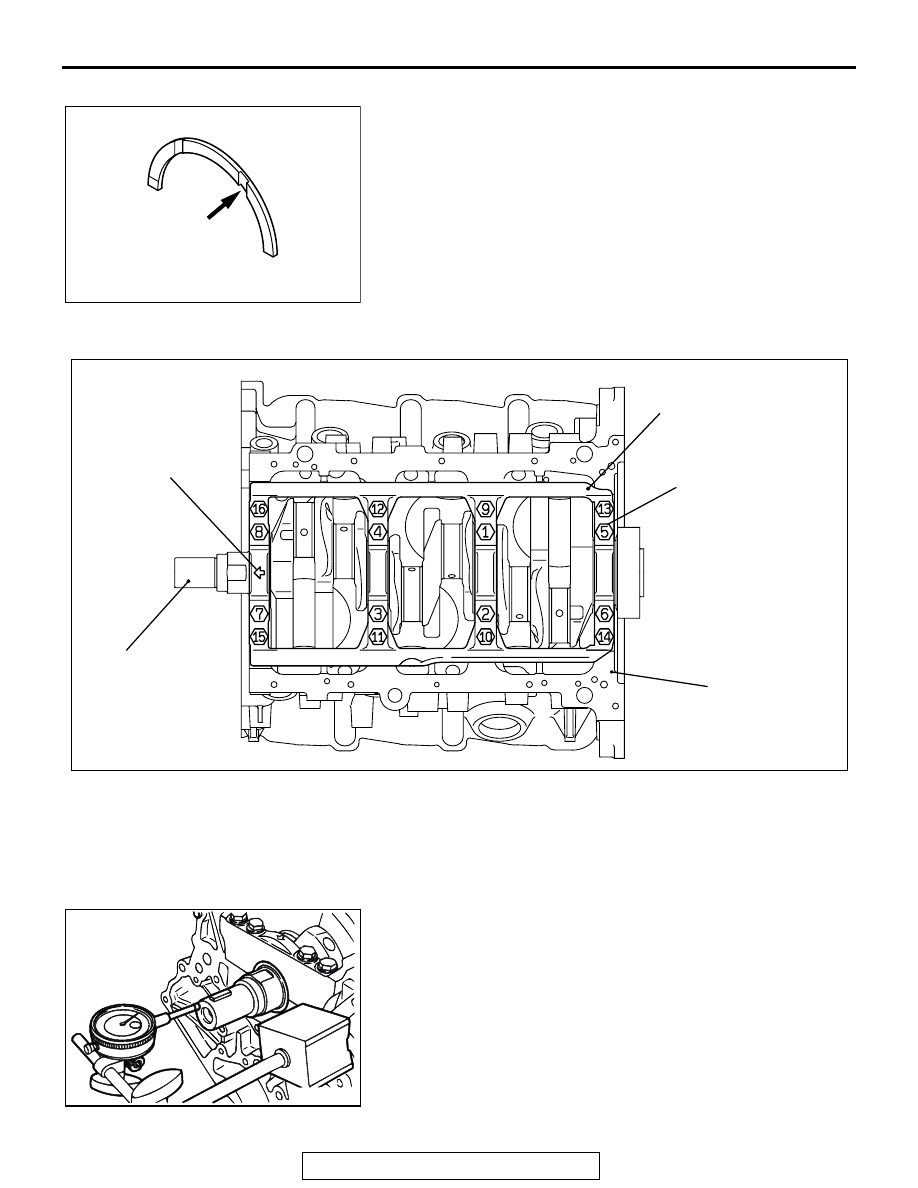
>>D<< CRANKSHAFT THRUST BEARING INSTALLATION
1. Install the thrust bearing in the No.3 bearing bore in the 

cylinder block and in the bearing cap. For easier installation, 
apply engine oil to the bearings; this will help hold them in 
position.

2. The thrust bearings must be installed with their groove 

toward the crankshaft web.

.

>>E<< BEARING CAP/BEARING BOLT INSTALLATION

1. Attach the bearing cap on the cylinder block as shown in the 

illustration.

2. Tighten the bearing cap bolts to specified torque in the 

sequence shown in the illustration.

Tightening torque: 74 

± 4 Nm (54 ± 3 ft-lb)

3. Check that the crankshaft rotates smoothly.
4. Check the end play. If it exceeds the limit value, replace the 

thrust bearing.

Standard value: 0.05 

 0.25 mm (0.002  0.009 inch)

Limit: 0.3 mm (0.01 inch)

.

AKX01393AB

GROOVE

THRUST
BEARING

AKX01395AB

FRONT MARK

BEARING CAP BOLT

NUMBERS ARE

TIGHTENING SEQUENCE

BEARING CAP

CRANKSHAFT

CYLINDER BLOCK

AK201528

CRANKSHAFT AND CYLINDER BLOCK

TSB Revision

ENGINE OVERHAUL <3.8L ENGINE>

11D-58

>>F<< CRANKSHAFT REAR OIL SEAL INSTALLATION
Using special tool MD998718, press-fit a new crankshaft rear 
oil seal into the oil seal case.

.

>>G<< OIL SEAL CASE INSTALLATION
1. Apply the sealant Mitsubishi Genuine Part number 

MD970389 or equivalent to the oil seal case.

2. Apply a small amount of engine oil to the entire 

circumference of the oil seal lip section, and place the oil 
seal case on the cylinder block.
NOTE: Install the oil seal case within 15 minutes after apply-
ing liquid gasket.Then wait at least one hour. Do not start the 
engine or let engine oil or coolant touch the sealant during 
that time.

INSPECTION

M1113008800322

.

CRANKSHAFT JOURNAL OIL CLEARANCE 
<PLASTIC GAUGING MATERIAL METHOD>
1. Remove oil from the crankshaft journal and crankshaft 

bearing inner surface.

2. Install the crankshaft.
3. Cut plastic gauging material to the same length as the width 

of the bearing and place it on the journal in parallel with its 
axis.

AKX00693

MD998718

OIL SEAL 
CASE

AB

AK201083

AK101043AB

PLASTIC
GAUGING
MATERIAL

CRANKSHAFT AND CYLINDER BLOCK

TSB Revision

ENGINE OVERHAUL <3.8L ENGINE>

11D-59

4. Install the crankshaft bearing cap carefully and tighten the 

bolts to the specified torque.

Tightening torque: 74 

± 4 Nm (54 ± 3 ft-lb)

5. Carefully remove the crankshaft bearing cap.
6. Measure the width of the smashed plastic gauging material 

at its widest section by using a scale printed on the plastic 
gauging material bag.

Standard value:

0.02 

 0.03 mm (0.0008  0.0012 inch) <No.1, 4>

0.03 

 0.04 mm (0.0012  0.0016 inch) <No.2, 3>

Limit: 0.1 mm (0.003 inch)

.

CRANKSHAFT REAR OIL SEAL
1. Check the oil seal lip for wear and damage.
2. Check the rubber for deterioration or hardening.
3. Check the oil seal case for cracks and damage.

.

CYLINDER BLOCK
1. Visually check for scratches, rust, and corrosion. Use a flaw 

detecting agent for the check. If defects are evident, correct 
or replace.

2. Using a straightedge and feeler gauge, check the block top 

surface for warpage. Make sure that the surface is free from 
gasket chips and other foreign matter.

Standard value: 0.05 mm (0.002 inch)
Limit: 0.1 mm (0.003 inch)

3. If the distortion is excessive, correct within the allowable 

limit or replace.

Grinding limit: *0.2 mm (0.008 inch)
 *Includes/combined with cylinder head grinding.
Cylinder block height (when new):

227.9 

 228.1 mm (8.972  8.980 inches)

4. Check the cylinder walls for scratches and seizure. If defects 

are evident, correct (bored to an oversize) or replace.

5. Using a cylinder gauge, measure the cylinder bore and 

cylindricality. If worn badly, correct by boring the cylinders to 
an oversize and replace pistons and piston rings. Measure 
at the points shown in the illustration.

Standard value: 

Cylinder Inside Diameter: 95.0 mm (3.740 inches) 
Cylindricality: 0.01 mm (0.0003 inch)

.

AK201526

AKX00738

AKX00739AB

12 mm (0.47 in)

BOTTOM

CENTER

CRANKSHAFT AND CYLINDER BLOCK

TSB Revision

ENGINE OVERHAUL <3.8L ENGINE>

11D-60

BORING CYLINDER 
1. Oversize pistons to be used should be determined on the 

basis of the largest bore cylinder.

     Piston size identification

NOTE: Size mark is stamped on the piston top.

2. Measure the outside diameter of the piston to be used. 

Measure it in the thrust direction as shown.

3. Based on the measured piston Outside Diameter (OD), 

calculate the boring finish dimension.

Boring finish dimension = Piston OD + (clearance 
between piston OD and cylinder) 

 0.02 mm (0.0008 

inch) (honing margin)

CAUTION

To prevent distortion that may result from temperature rise 
during honing, bore cylinders in the order of number 2, 
number 4, number 6, number 1, number 3 and number 5.
4. Bore all cylinders to the calculated boring finish dimension.
5. Hone to the final finish dimension (piston OD + clearance 

between piston OD and cylinder).

Standard value: 

Cylinder Inside Diameter: 95.0 mm (3.740 inches) 
Cylindricality: 0.01 mm (0.0003 inch)

6. Check the clearance between the piston and cylinder.

Clearance between piston and cylinder:

0.02 

 0.04 mm (0.0008  0.0015 inch)

NOTE: When boring cylinders, finish all six cylinders to the 
same oversize. Do not bore only one cylinder to an oversize.

SIZE

IDENTIFICATION MARK

0.25 mm (0.010 in) Oversize 
diameter

0.25

0.50 mm (0.020 in) Oversize 
diameter

0.50

AKX00740

PISTON OUTSIDE
DIAMETER

THRUST 
DIRECTION

AB


Content   ..  608  609  610  611   ..