Mitsubishi Galant (2004+). Manual - part 607
PISTON AND CONNECTING ROD
TSB Revision
ENGINE OVERHAUL <3.8L ENGINE>
11D-45
3. Check the body clearance.
Standard value: 0.10
− 0.18 mm (0.004 − 0.007 inch)
Limit: 0.35 mm (0.013 inch)
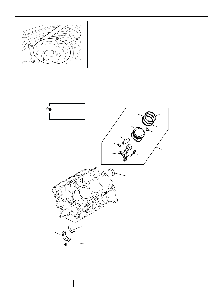
PISTON AND CONNECTING ROD
REMOVAL AND INSTALLATION
M1113008400636
AKX00745
AK201085
1
2
3
4
5
6
7
8
9
10
11
12
13
14
27 ± 2 N·m
20 ± 1 ft-lb
+ 90˚ TO 94˚
AC
APPLY ENGINE OIL
TO ALL MOVING
PARTS BEFORE
INSTALLATION.
REMOVAL STEPS
>>G<<
1. CONNECTING ROD CAP NUT
<<A>> >>F<<
2. CONNECTING ROD CAP
>>D<<
3. CONNECTING ROD BEARING,
LOWER
>>E<<
4. PISTON AND CONNECTING ROD
ASSEMBLY
>>D<<
5. CONNECTING ROD BEARING,
UPPER
REMOVAL STEPS (Continued)