Mitsubishi Galant (2004+). Manual - part 604


  Index      Mitsubishi     Mitsubishi Galant - service repair manual 2004 year


Search            


Content   ..  602  603  604  605   ..


Mitsubishi Galant (2004+). Manual - part 604


CYLINDER HEAD AND VALVES

TSB Revision

ENGINE OVERHAUL <3.8L ENGINE>

11D-33

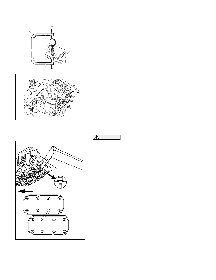
>>C<< RETAINER LOCK INSTALLATION
Using special tool  MD998735 or MD998772, compress the 
valve spring and insert the retainer lock into position.
NOTE: The valve spring, if excessively compressed, causes 
the bottom end of retainer to damage the stem seal.

.

>>D<< CYLINDER HEAD BOLT INSTALLATION

CAUTION

Attach the head bolt washer in the direction shown in the 
figure.
1. Tighten the bolts in the illustrated sequence two or three 

steps.

Tightening torque: 108 

± 5 Nm (80 ± 4 ft-lb)

2. Back off the bolts once and tighten them again to the 

specified torque in step1.

AK100166

MD998735

AB

AKX00617

MD998772

AB

AKX01452AB

FRONT

MD998051

HEAD
BOLT
WASHER

RIGHT
BANK

LEFT
BANK

CYLINDER HEAD AND VALVES

TSB Revision

ENGINE OVERHAUL <3.8L ENGINE>

11D-34

INSPECTION

M1113007000464

.

CYLINDER HEAD
1. Check the cylinder head gasket surface for flatness by using 

a straightedge in the directions of A through G shown in the 
illustration.

Standard value: 0.03 mm (0.0012 inch) 
Limit: 0.2 mm (0.007 inch)

2. If the service limit is exceeded, correct to meet the 

specification.

Grinding limit: *0.2 mm (0.007 inch)

3.  *If the service limit is exceeded, correct to meet the 

specification.

Cylinder head height (specification when new):

120 mm (4.7 inches)

.

VALVE
1. Check the valve face for correct contact. If incorrect, reface 

using a valve refacer. The valve should make a uniform 
contact with the seat at the center of the valve face.

2. If the margin exceeds the service minimum limit, replace the 

valve.

Standard value:

<Intake> 1.0 mm (0.04 inch)
<Exhaust> 1.2 mm (0.05 inch)

Minimum limit:

<Intake> 0.5 mm (0.02 inch)
<Exhaust> 0.7 mm (0.03 inch)

3. Measure the valve's total length. If the measurement is less 

than specified, replace the valve.

Standard value:

<Intake> 110.30 mm (4.343 inches)
<Exhaust> 112.11 mm (4.414 inches)

Minimum limit:

<Intake> 109.80 mm (4.323 inches)
<Exhaust> 111.61 mm (4.394 inches)

.

VALVE SPRINGS
1. Measure the free height of the spring and, if it is smaller than 

the minimum limit, replace the spring.

Standard value: 51.0 mm (2.01 inches)
Minimum limit: 50.0 mm (1.97 inches)

2. Measure the squareness of the spring and, if the limit is 

exceeded, replace the spring.

Standard value: 2

° or less

Limit: 4

°

AKX00733

AKX00619

MARGIN

VALVE SEAT 
CONTACT

AB

AKX00624

AKX00607

FREE
HEIGHT

AB

CYLINDER HEAD AND VALVES

TSB Revision

ENGINE OVERHAUL <3.8L ENGINE>

11D-35

.

VALVE GUIDES
Measure the clearance between the valve guide and valve 
stem. If the limit is exceeded, replace the valve guide, valve, or 
both.

Standard value:

<Intake> 0.02 

 0.05 mm (0.0008  0.0019 inch)

<Exhaust> 0.04 

 0.06 mm (0.0016  0.0023 inch)

Limit:

<Intake> 0.10 mm (0.003 inch)
<Exhaust> 0.15 mm (0.005 inch)

.

VALVE SEAT
Assemble the valve, then measure the valve stem projection 
between the end of the valve stem and the spring seating sur-
face. If the measurement exceeds the specified limit, replace 
the valve seat.

Standard value:

<Intake> 48.30 mm (1.902 inches)
<Exhaust> 51.71 mm (2.036 inches)

Limit:

<Intake> 48.80 mm (1.921 inches)
<Exhaust> 52.21 mm (2.056 inches)

.

VALVE SEAT RECONDITIONING PROCEDURE

CAUTION

Before correcting the valve seat, check the clearance 
between the valve guide and valve and, if necessary, 
replace the valve guide.
1. Using the special tool or a seat grinder, correct to obtain the 

specified seat width and angle.

2. After correcting the valve seat, lap the valve and valve seat 

using lapping compound. Then, check the valve stem 
projection.

.

AKX00714

VALVE 
GUIDE

STEM OUTSIDE 
DIAMETER

GUIDE INSIDE DIAMETER

AB

AKX00695

SPRING SEATING
SURFACE

VALVE STEM END

VALVE STEM
PROJECTION

AB

AK101830AB

0.9 – 1.3 mm
(0.04 – 0.05 in)

65˚

65˚

15˚

25˚

43.5˚ – 44˚

0.9 – 1.3 mm
(0.04 – 0.05 in)

CYLINDER HEAD AND VALVES

TSB Revision

ENGINE OVERHAUL <3.8L ENGINE>

11D-36

VALVE SEAT REPLACEMENT PROCEDURE

CAUTION

Before replacing the valve seat, check the valve guide and, 
if necessary, replace the valve guide.
1. Cut the valve seat from the inside to thin the wall thickness. 

Then, remove the valve seat.

2. Rebore the valve seat hole in the cylinder head to a selected 

oversize valve seat diameter.

Seat ring hole diameter:

Intake valve

0.3 oversize 37.80 

 37.83 mm (1.4882  1.4894 

inches)
0.6 oversize 38.10 

 38.13 mm (1.5000  1.5012 

inches)

Exhaust valve

0.3 oversize 34.80 

 34.83 mm (1.3701  1.3713 

inches)
0.6 oversize 35.10 

 35.13 mm (1.3819  1.3831 

inches)

3. Before fitting the valve seat, either heat the cylinder head up 

to approximately 250

°C (482°F) or cool the valve seat in 

liquid nitrogen, to prevent the cylinder head bore from 
galling.

4. Using a valve seat cutter, correct the valve seat to the 

specified width and angle. Using a valve seat cutter, correct 
the valve seat to the specified width and angle. See "VALVE 
SEAT RECONDITIONING PROCEDURE" on the previous 
page.

.

VALVE GUIDE REPLACEMENT PROCEDURE
1. Remove the snap ring from the exhaust valve guide.
2. Using a press, remove the valve guide toward the cylinder 

head gasket surface.

CAUTION

Do not install a valve guide of the same size again.
3. Re-bore the valve guide hole of the cylinder head so that it 

fits the press-fitted oversize valve guide.

Valve guide hole diameter:

0.05 oversize 11.05 

 11.07 mm (0.4350  0.4358 inch)

0.25 oversize 11.25 

 11.27 mm (0.4429  0.4437 inch)

0.50 oversize 11.50 

 11.52 mm (0.4528  0.4535 inch)

4. Install the new snap ring into the groove of exhaust valve 

guide.

AKX00610

0.5 – 1 mm 
(0.020 – 0.039 in)

0.5 – 1 mm (0.020 – 0.039 in)

CUT
AWAY

AB

AKX00611

HEIGHT OF 
SEAT RING

OVERSIZE DIAMETER

AB

AKX00712

REMOVAL

INSTALLATION

PRESS

PRESS

PUSH ROD

VALVE 
GUIDE

VALVE 
GUIDE

AB


Content   ..  602  603  604  605   ..