Mitsubishi Galant (2004+). Manual - part 551


  Index      Mitsubishi     Mitsubishi Galant - service repair manual 2004 year


Search            


Content   ..  549  550  551  552   ..


Mitsubishi Galant (2004+). Manual - part 551


DRIVE SHAFT ASSEMBLY

TSB Revision

FRONT AXLE

26-23

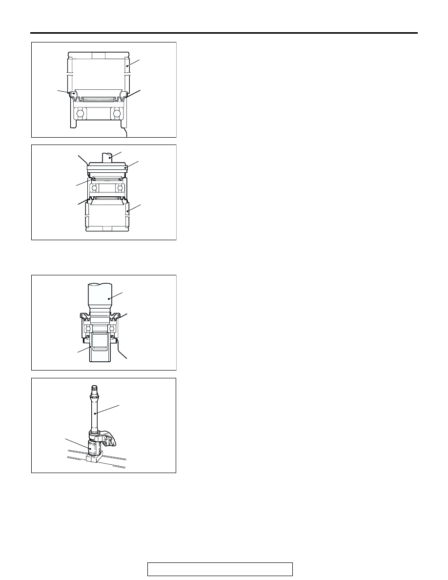
2. Use special tools MB990890, MB990938, and MB990934 to 

press the dust seals into the center bearing bracket until 
they are flush with each other.

3. Apply repair kit grease to the lip of each dust seal.

.

>>E<<INNER SHAFT <3.8L-RH> INSTALLATION
1. Use special tool MB991172 to hold the center bearing inner 

race, and then press-in the inner shaft.

2. Apply repair kit grease to the inner shaft spline, then press fit 

it into the PTJ case.
NOTE: When press-fitting the inner shaft into the PTJ case, 
apply a thin coat of repair kit grease to the dust seal outer lip 
part and the outside edge of the PTJ axial part.

.

AC101696

MB990890

DUST
SEAL
INNER

AC

AC101697

MB990938

MB990934

MB990890

DUST SEAL
OUTER

AC

AC101698

MB991172

INNER SHAFT

AC

AC205847

AC305786

PTJ CASE

INNER SHAFT

AB

DRIVE SHAFT ASSEMBLY

TSB Revision

FRONT AXLE

26-24

>>F<< TJ CASE <2.4L>/PTJ CASES <3.8L> INSTALLATION

CAUTION

The drive shaft joint use special grease. Do not mix old 
and new or different types of grease.
After applying the specified grease to the TJ case or PTJ case, 
insert the drive shaft and apply grease again.

Specified grease: Repair kit grease

Amount to use <2.4L-LH>: 140 

± 10 g (4.9 ± 0.3 

ounces) 

Amount to use <2.4L-RH>: 130 

± 10 g (4.6 ± 0.3 

ounces)

Amount to use <3.8L>: 220 

± 10 g (7.8 ± 0.3 ounces)

NOTE: The grease in the repair kit should be divided in half for 
use, respectively, at the joint and inside the boot.

.

>>G<< TJ BOOT BAND (SMALL) <2.4L>/PTJ BOOT BAND 
(SMALL) <3.8L>/TJ BOOT BAND (LARGE) <2.4L>/PTJ 
BOOT BAND (LARGE) <3.8L> INSTALLATION
Set the TJ boot bands or PTJ boot bands at the specified dis-
tance in order to adjust the amount of air inside the TJ boot or 
PTJ boot, and then tighten the TJ boot band (small) or PTJ 
boot band (small), TJ boot band (large) or PTJ boot band 
(large) securely.

Standard value (A): 85 

± 3 mm (3.35 ± 0.12 inches)

INSPECTION

M1261003800163

• Check the drive shaft for damage, bending or corrosion.

• Check the inner shaft for damage, bending or corrosion.

• Check the drive shaft spline part for wear or damage.

• Check the inner shaft spline part for wear or damage.

• Check the spider assembly for roller rotation, wear or corro-

sion.

• Check the groove inside TJ case or PTJ case for wear or 

corrosion.

• Check the boots for deterioration, damage or cracking.

• Check the center bearing for seizure, discoloration or 

roughness of rolling surface.

• Check the dust cover for damage or deterioration.

AC102656 AC

AC102657

A

AC

DRIVE SHAFT ASSEMBLY

TSB Revision

FRONT AXLE

26-25

BJ BOOT REPLACEMENT

M1261005200394

Required Special Tool:
MB991561:Boot Band Crimping Tool
1. Remove the boot bands (large and small).

NOTE: The boot bands cannot be re-used.

2. Remove the BJ boot.
3. Wrap a plastic tape around the shaft spline, and assemble 

the boot band and BJ boot.

4. Align the center groove on the BJ boot small end with the 

shaft groove.

5. Turn the adjusting bolt on special tool MB991561 so that the 

size of the opening (W) is at the standard value.

Standard value (W): 2.9 mm (0.11 inch)

<If it is larger than 2.9 mm (0.11 inch)> Tighten the 

adjusting bolt.

<If it is smaller than 2.9 mm (0.11 inch)> Loosen the 

adjusting bolt.

NOTE: The value of W will change by approximately 0.7 mm 
(0.03 inch) for each turn of the adjusting bolt.
NOTE: The adjusting bolt should not be turned more than 
once.

6. Position the BJ boot band (small) so that there is even 

clearance at either end (A and B).

AC102658

AC102659

AC102660

W

MB991561

STOPPER

ADJUSTING BOLT

AC

AC102661AC

BOOT

A

BOOT BAND
(SMALL)

B

PROJECTION

DRIVE SHAFT ASSEMBLY

TSB Revision

FRONT AXLE

26-26

CAUTION

• Secure the drive shaft in an upright position and clamp 

part of the boot band to be crimped securely in the jaws 
of special tool MB991561.

• Crimp the boot band until the special tool touches the 

stopper.

7. Use special tool MB991561 to crimp the boot band (small).

8. Check that the crimping amount (C) of the boot band is at 

the standard value.

Standard value (D): 2.4 

 2.8 mm (0.09  0.11 inch)

<If the crimping amount is larger than 2.8 mm (0.11 

inch)>
Readjust the value of (W) in step 5 according to the 
following formula, and then repeat the operation in 
step 7.
W = 5.5 mm (0.22 inch) 

 D

Example: If D = 2.9 mm (0.11 inch), then W = 2.6 mm 
(0.10 inch).

<If the crimping amount is smaller than 2.4 mm (0.09 

inch)>
Remove the EBJ boot band, readjust the value of 
(W) in step 5 according to the following formula, 
and then repeat the operations in steps 6 and 7 
using a new EBJ boot band.
W = 5.5 mm (0.22 inch) 

 D

Example: If D = 2.3 mm (0.09 inch), then W = 3.2 
mm (0.13 inch).

9. Check that the boot band is not sticking out past the place 

where it has been installed. If the boot band is sticking out, 
remove it and then repeat steps 6 to 8, using a new boot 
band.

CAUTION

The drive shaft joint uses special grease. Do not mix old 
and new or different types of grease.
10.Fill the inside of the boot with the specified amount of the 

specified grease.

Specified grease: Repair kit grease

Amount to use <2.4L>: 120 

± 10 g (4.2 ± 0.3 ounces)

Amount to use <3.8L>: 165 

± 10 g (5.8 ± 0.3 ounces)

AC102663 AC

MB991561

AC102662

C

AD


Content   ..  549  550  551  552   ..