Mitsubishi Galant (2004+). Manual - part 530


  Index      Mitsubishi     Mitsubishi Galant - service repair manual 2004 year


Search            


Content   ..  528  529  530  531   ..


Mitsubishi Galant (2004+). Manual - part 530


ANTI-LOCK BRAKING SYSTEM (ABS) DIAGNOSIS

TSB Revision

ANTI-LOCK BRAKING SYSTEM (ABS)

35B-65

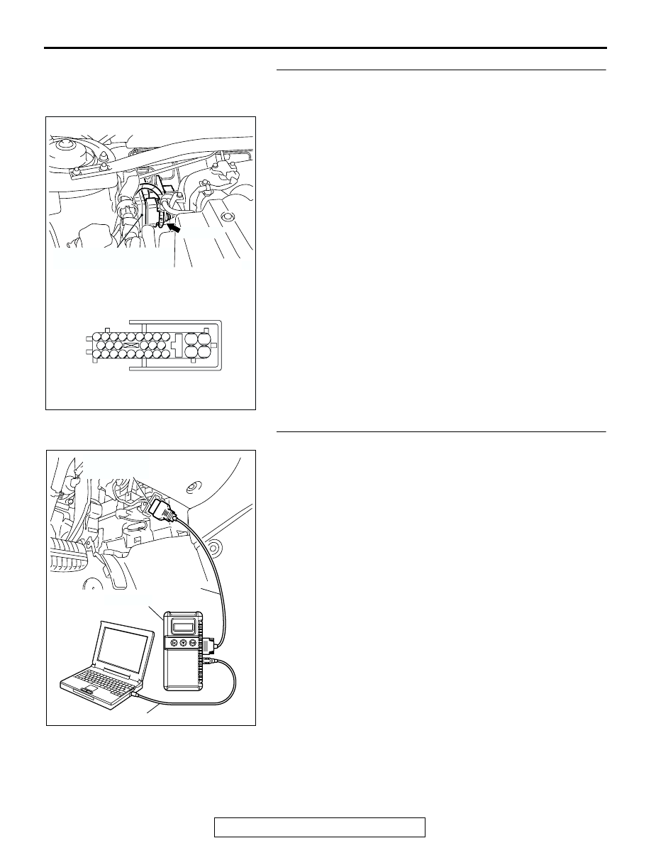
STEP 6. Check ABS-ECU connector A-02  for loose, 
corroded or damaged terminals, or terminals pushed back 
in the connector.

Q: Is ABS-ECU connector A-02 damaged?

YES : Repair or replace the damaged component(s). Refer 

to GROUP 00E, Harness Connector Inspection 

P.00E-2

. Then go to Step 8.

NO :  An open circuit may be present in the ground circuit. 

Repair the wiring harness between ABS-ECU 
connector A-02 terminal 2 and the body ground. Then 
go to Step 8.

STEP 7. Recheck for diagnostic trouble code.

Check again if the DTC is set.
(1) Turn the ignition switch to the "ON" position.
(2) Erase the DTC.

(3) Turn the ignition switch to the "LOCK" (OFF) position.
(4) Turn the ignition switch to the "ON" position.
(5) Check if the DTC is set.
(6) Turn the ignition switch to the "LOCK" (OFF) position.
Q: Is DTC C1278 or C1279 set?

YES : Replace the hydraulic unit (integrated with 

ABS-ECU). Then go to Step 8.

NO :  It can be assumed that this malfunction is intermittent. 

Refer to GROUP 00, How to Use 
Troubleshooting/Inspection Service Points 

− How to 

Cope with Intermittent Malfunction 

P.00-6

.

AC306406

19

2

18

1

8

9

7

6

5

4

3

10

11   

25

15

16

17

27

28

26

12

13

14

23

24

22 21 20

A-02 HARNESS CONNECTOR
(HARNESS SIDE)

AB

A-02 (GR)

CONNECTOR: A-02

HYDRAULIC UNIT
(WITH BUILT-IN ABS-ECU)

AC305412

AB

MB991910

DATA LINK

CONNECTOR

MB991824

MB991827

ANTI-LOCK BRAKING SYSTEM (ABS) DIAGNOSIS

TSB Revision

ANTI-LOCK BRAKING SYSTEM (ABS)

35B-66

STEP 8. Recheck for diagnostic trouble code.

Check again if the DTC is set.
(1) Turn the ignition switch to the "ON" position.
(2) Erase the DTC.
(3) Turn the ignition switch to the "LOCK" (OFF) position.
(4) Turn the ignition switch to the "ON" position.
(5) Check if the DTC is set.
(6) Turn the ignition switch to the "LOCK" (OFF) position.
Q: Is DTC C1278 or C1279 set?

YES : Go to Step 1.
NO :  The procedure is complete.

AC305412

AB

MB991910

DATA LINK

CONNECTOR

MB991824

MB991827

ANTI-LOCK BRAKING SYSTEM (ABS) DIAGNOSIS

TSB Revision

ANTI-LOCK BRAKING SYSTEM (ABS)

35B-67

DTC C1395: Brake fluid filling not completed

COMBINATION
METER

CPU

CAN-LINE

ABS-ECU
OR
ABS/TCL-ECU

JOINT
CONNECTOR
(1)

PARKING
BRAKE
SWITCH

BRAKE FLUID
LEVEL SWITCH

2.4L ENGINE

3.8L ENGINE

Brake Fluid Level Switch and Parking Brake Switch Circuit

AC309288

ANTI-LOCK BRAKING SYSTEM (ABS) DIAGNOSIS

TSB Revision

ANTI-LOCK BRAKING SYSTEM (ABS)

35B-68

CAUTION

If there is any problem in the CAN bus lines, an 
incorrect diagnostic trouble code may be set. 
Prior to this diagnosis, diagnose the CAN bus 
lines.

.

CIRCUIT OPERATION
The meter ECU detects the brake fluid level switch 
ON/OFF and controls the brake warning light 
ON/OFF.

.

ABS DTC SET CONDITIONS
This DTC is set when all of the following cases are 
met.

• When the amount of the brake fluid is less than 

lower limit.

• When the stop light switch is OFF.

• When the vehicle speed is 30km/h or more and 

90km/h or less.

• The acceleration G is 0.03 G or more.  

• The other DTCs is not set.

.

TROUBLESHOOTING HINTS (The most likely 
causes for these DTCs are to set are:)

Current trouble

• Damaged wiring harness or connector

• Malfunction of stop light switch

• Malfunction of parking brake switch

• Malfunction of the hydraulic unit (integrated with 

ABS-ECU)

• Malfunction of the combination meter (integrated 

with meter ECU)

.

Past trouble

• Carry out diagnosis with particular emphasis on 

connector(s) or wiring harness between the com-
bination meter circuit (terminal 7) to the brake 
fluid level switch or parking brake switch. For 
diagnosis procedures, refer to "How to cope with 
past trouble" (Refer to GROUP 00, How to Use 
Troubleshooting/Inspection Service Points 

P.00-6

).

.

DIAGNOSIS

Required Special Tools:

• MB991958: Scan Tool (MUT-III Sub Assembly)

• MB991824: Vehicle Communication Interface (V.C.I.)

• MB991827: MUT-III USB Cable

• MB991910: MUT-III Main Harness A

• MB991970: ABS Check Harness

AC305210

CONNECTOR: A-13

AU

A-13 (GR)

AC305229AG

B-07 (GR)

CONNECTOR: B-07

AC305231

CONNECTORS: C-01, C-29, C-101

DF

C-101

C-01

C-29

AC305233

CONNECTOR: C-18

CS

C-18 (B)


Content   ..  528  529  530  531   ..