Mitsubishi Galant (2004+). Manual - part 499


  Index      Mitsubishi     Mitsubishi Galant - service repair manual 2004 year


Search            


Content   ..  497  498  499  500   ..


Mitsubishi Galant (2004+). Manual - part 499


DIAGNOSIS

TSB Revision

CONTROLLER AREA NETWORK (CAN)

54C-607

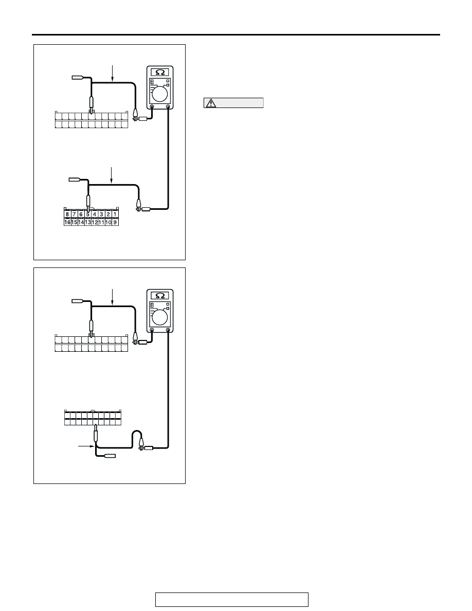
(5) Measure the resistance between joint connector (3) 

terminal 6 and A/C-ECU connector terminal 5 <manual air 

conditioning system (low)> or 15 <manual air conditioning 
system (middle) or automatic air conditioning system>.

OK: 2 ohms or less

CAUTION

Strictly observe the specified wiring harness repair proce-
dure. For details refer to 

P.54C-5

.

Q: Do all the resistances measure 2 ohms or less?

YES : If all the resistances measure 2 ohms or less, power 

supply to the A/C-ECU may be suspected. Diagnose 
the air conditioning system. Refer to GROUP 55A, 
Manual A/C diagnosis 

P.55A-246

.

NO :  If either of the resistances measures more than 2 

ohms or all the resistances measure more than 2 
ohms, repair the wiring harness between joint 
connector (3) and the A/C-ECU connector. 

AC204582

11

22

10

21

9

20

8

19

7

18

6

17

5

16

4

15

3

14

2

13

1

12

CH

TEST HARNESS

TEST HARNESS

HARNESS SIDE: C-02

HARNESS SIDE: C-10

AC204582

8

2

10 9

1

5

3

4

6

7

20191817161514131211

TEST 
HARNESS

CI

HARNESS SIDE: C-15

11

22

10

21

9

20

8

19

7

18

6

17

5

16

4

15

3

14

2

13

1

12

TEST HARNESS

HARNESS SIDE: C-02

DIAGNOSIS

TSB Revision

CONTROLLER AREA NETWORK (CAN)

54C-608

DIAGNOSTIC ITEM 23: Diagnose the lines between CAN main bus line and the SRS-ECU.

CAUTION

When servicing a CAN bus line, ground yourself 
by touching a metal object such as an unpainted 
water pipe. If you fail to do so, a component con-
nected to the CAN bus line may be damaged.

JOINT
CONNECTOR (3)

COMBINATION
METER

SRS-ECU

POWERTRAIN
CONTROL MODULE

<WITHOUT ELECTRONIC BRAKE-FORCE DISTRIBUTION (EBD)
 AND ANTI-LOCK BRAKING SYSTEM (ABS)>

DIAGNOSIS

TSB Revision

CONTROLLER AREA NETWORK (CAN)

54C-609

.

JOINT
CONNECTOR (3)

COMBINATION
METER

SRS-ECU

POWERTRAIN
CONTROL MODULE

<WITH ELECTRONIC BRAKE-FORCE DISTRIBUTION (EBD)
 AND ANTI-LOCK BRAKING SYSTEM (ABS)>

ABS-ECU

AC305231BD

CONNECTOR: C-02

AC305233 AT

CONNECTORS: C-22, C-121

C-121 (Y)

C-22 (Y)

DIAGNOSIS

TSB Revision

CONTROLLER AREA NETWORK (CAN)

54C-610

TROUBLE JUDGMENT
If the MUT-III cannot received signals from the 
SRS-ECU, CAN bus line connector(s) are broken or 
an open circuit has occurred.

.

COMMENTS ON TROUBLE SYMPTOM
The wiring harness wire or connectors may have 
loose, corroded, or damage terminals, or terminals 
pushed back in the connector, or the SRS-ECU may 
be defective.

.

TROUBLESHOOTING HINTS

• The wiring harness or connectors may have 

loose, corroded, or damage terminals, or termi-
nals pushed back in the connector

• The SRS-ECU may be defective

DIAGNOSIS

Required Special Tool:

• MB991223: Harness Set

STEP 1. Check intermediate connector C-22 and SRS-ECU 
connector C-121 for loose, corroded or damaged 
terminals, or terminals pushed back in the connector.

CAUTION

The strand end of the twisted wire should be within 10 cm 
(4 inches) from the connector. For details refer to 

P.54C-4

.

Q: Are intermediate connector C-22 and SRS-ECU 

connector C-121 in good condition?
YES : 
Go to Step 2.
NO :  Repair the damaged parts. Replace the joint 

connector as necessary.

AC305234AC

CONNECTORS: C-22, C-121

C-121 HARNESS SIDE

C-121 (Y)

C-22 (Y)

C-22

48

21

22

23

24

25

26

27

28

29

30

31

32

33

34

35

36

37

38

39

40

41

42

43

44

45

46

47


Content   ..  497  498  499  500   ..