Mitsubishi Galant (2004+). Manual - part 481
DIAGNOSIS
TSB Revision
CONTROLLER AREA NETWORK (CAN)
54C-535
.
TROUBLE JUDGMENT
If the MUT-III cannot received signals from ECUs,
CAN bus line connector(s) are broken or an open cir-
cuit has occurred.
.
COMMENTS ON TROUBLE SYMPTOM
The wiring harness wire or connectors may have
loose, corroded, or damage terminals, or terminals
pushed back in the connector, or a ECU may be
defective.
.
TROUBLESHOOTING HINTS
• The wiring harness or connectors may have
loose, corroded, or damage terminals, or termi-
nals pushed back in the connector
• The ETACS-ECU may be defective
• The combination meter may be defective
• The A/C-ECU may be defective
• The SRS-ECU may be defective
• The multi-center display unit (middle-grade type)
may be defective
• The ABS-ECU may be defective
• The powertrain control module may be defective
AC305206
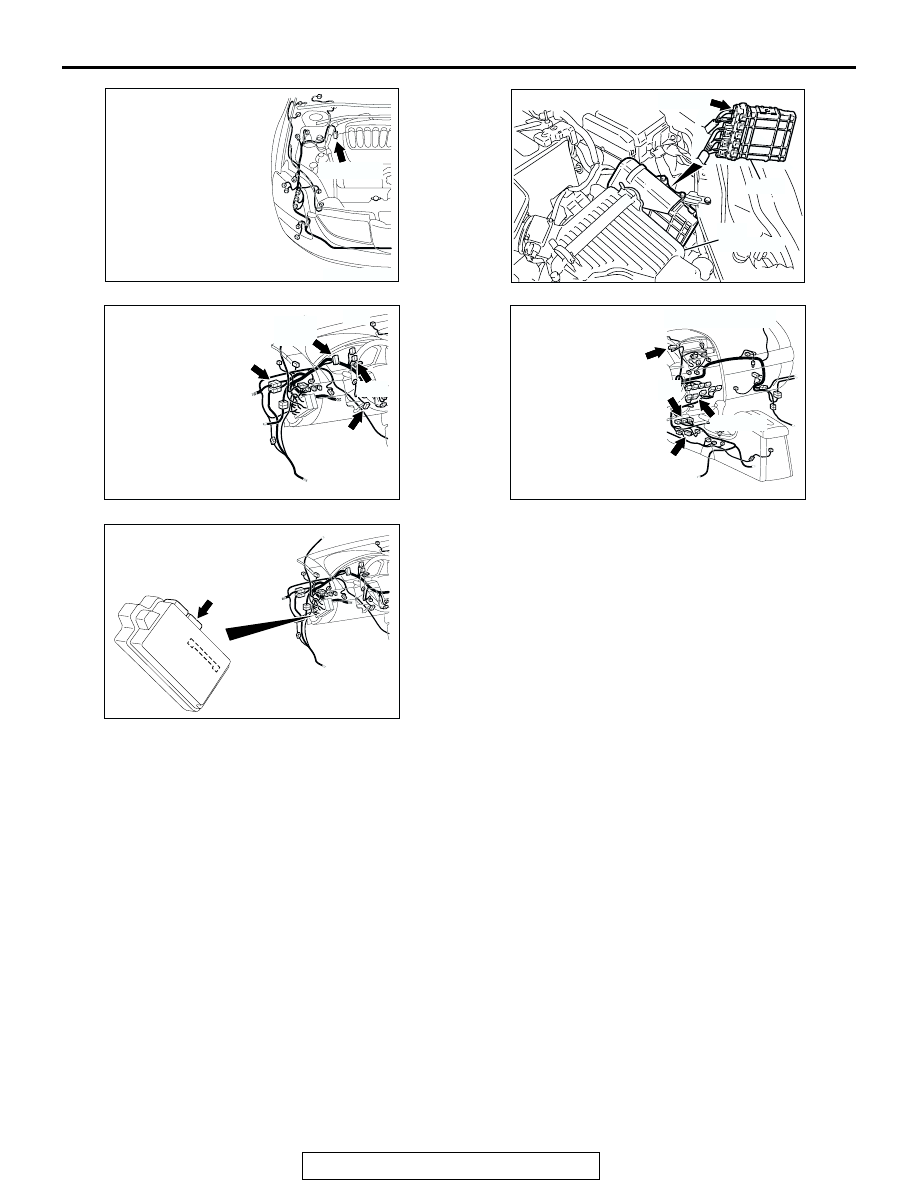
CONNECTOR: A-02
AR
A-02 (GR)
AC306248AB
B-19 (B)
CONNECTOR: B-19
AIR
CLEANER
PCM
AC305231BZ
C-101
C-125 (B)
C-29
C-02
CONNECTORS: C-02, C-29, C-101, C-125
AC305233AV
CONNECTORS: C-05, C-15, C-22, C-121
C-121 (Y)
C-22 (Y)
C-15 (B)
C-05 (B)
AC305413
C-218 (GR)
CONNECTOR: C-218
AJ
JUNCTION BLOCK
(REAR VIEW)