Mitsubishi Galant (2004+). Manual - part 430


  Index      Mitsubishi     Mitsubishi Galant - service repair manual 2004 year


Search            


Content   ..  428  429  430  431   ..


Mitsubishi Galant (2004+). Manual - part 430


DIAGNOSIS

TSB Revision

CONTROLLER AREA NETWORK (CAN)

54C-331

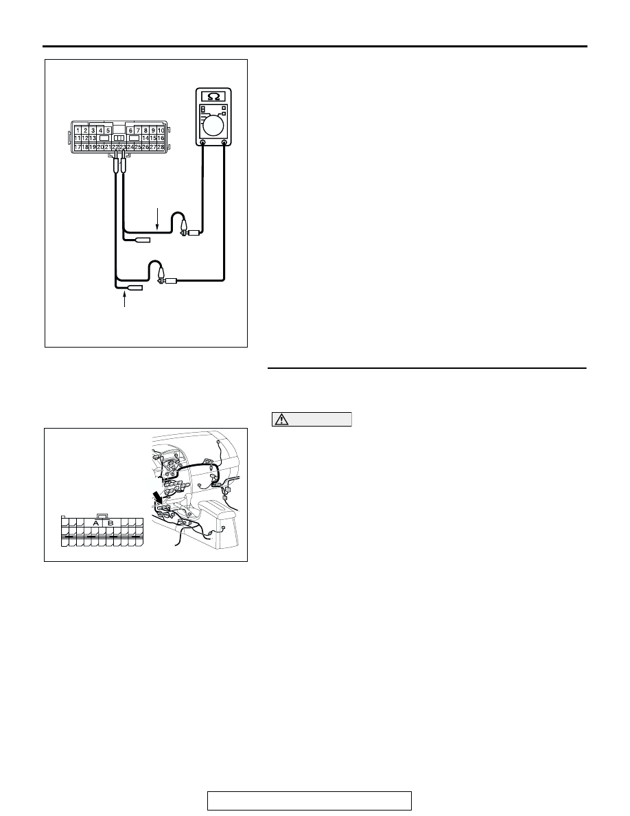
(4) Measure the resistance between intermediate connector 

terminals 22 and 23.

OK: 1 k

 or more

Q: Does the resistance measure 1 k

 or more?

YES : If the resistance measures 1 k

Ω or more, go to Step 

20  .

NO :  If the resistance measures less than 1 k

Ω, repair the 

wiring harness between intermediate connector C-29 
and SRS-ECU connector.

STEP 20. Check SRS-ECU connector C-121 for loose, 
corroded or damaged terminals, or terminals pushed back 
in the connector.

CAUTION

The strand end of the twisted wire should be within 10 cm 
(4 inches) from the connector. For details refer to 

P.54C-4

.

Q: Is SRS-ECU connector C-121 in good condition?

YES : Go to Step 21.
NO :  Repair the damaged parts.

AC204582

AC204582CS

MALE SIDE: C-22

TEST 
HARNESS

TEST HARNESS

AC305233 AJ

CONNECTOR: C-121

HARNESS SIDE

C-121 (Y)

48

21

22

23

24

25

26

27

28

29

30

31

32

33

34

35

36

37

38

39

40

41

42

43

44

45

46

47

DIAGNOSIS

TSB Revision

CONTROLLER AREA NETWORK (CAN)

54C-332

STEP 21. Check the SRS-ECU for short circuit. Measure 

the resistance at SRS-ECU connector C-121.

CAUTION

A digital multimeter should be used. For details refer to 

P.54C-4

.

(1) Disconnect SRS-ECU connector C-121, and measure the 

resistance at the component side of SRS-ECU connector 
C-121.

(2) Measure the resistance between SRS-ECU connector 

terminals 32 and 43.

OK: 1 k

 or more

Q: Does the resistance measure 1 k

 or more?

YES : If the resistance measures 1 k

Ω or more, diagnose 

CAN bus lines thoroughly by referring to 

P.54C-465

.

NO :  If the resistance measures less than 1 k

Ω, replace the 

SRS-ECU.

AC305233 AJ

CONNECTOR: C-121

HARNESS SIDE

C-121 (Y)

48

21

22

23

24

25

26

27

28

29

30

31

32

33

34

35

36

37

38

39

40

41

42

43

44

45

46

47

AC209438

48

21

22

23

24

25

26

27

28

29

30

31

32

33

34

35

36

37

38

39

40

41

42

43

44

45

46

47

AC209438

TEST 
HARNESS

AU

TEST 
HARNESS

COMPONENT SIDE: C-121

DIAGNOSIS

TSB Revision

CONTROLLER AREA NETWORK (CAN)

54C-333

STEP 22. Check the CAN_L and H lines (communication 
lines only) between joint connector (3) and the 
intermediate connector for a short circuit. Measure the 

resistance at joint connector (3) C-02.

CAUTION

A digital multimeter should be used. For details refer to 

P.54C-4

.

CAUTION

The test wiring harness should be used. For details refer to 

P.54C-4

.

(1) Disconnect intermediate connector C-22 and joint 

connector (3) C-02, and measure the resistance at the 
wiring harness side of joint connector (3) C-02.

(2) Turn the ignition switch to the "LOCK" (OFF) position.

CAUTION

Disconnect the negative battery terminal. For details refer 
to 

P.54C-4

.

(3) Disconnect the negative battery terminal.

(4) Measure the resistance between joint connector (3) 

terminals 3 and 14.

OK: 1 k

 or more

CAUTION

Strictly observe the specified wiring harness repair proce-
dure. For details refer to 

P.54C-5

.

Q: Does the resistance measure 1 k

 or more?

YES : If the resistance measures 1 k

Ω or more, diagnose 

CAN bus lines thoroughly by referring to 

P.54C-465

.

NO :  If the resistance measures less than 1 k

Ω, repair the 

wiring harness between intermediate connector C-22 
and joint connector (3).

AC305231AP

CONNECTOR: C-02

AC305233 AI

CONNECTOR: C-22

C-22 (Y)

AC209438

11

22

10

21

9

20

8

19

7

18

6

17

5

16

4

15

3

14

2

13

1

12

TEST 
HARNESS

AV

TEST 
HARNESS

HARNESS SIDE: C-02

DIAGNOSIS

TSB Revision

CONTROLLER AREA NETWORK (CAN)

54C-334

STEP 23. Check data link connector C-125 for loose, 
corroded or damaged terminals, or terminals pushed back 
in the connector.

CAUTION

The strand end of the twisted wire should be within 10 cm 
(4 inches) from the connector. For details refer to 

P.54C-4

.

Q: Is data link connector C-125 in good condition?

YES : Go to Step 24.
NO :  Repair the damaged parts.

STEP 24. Check the CAN_L and H lines (communication 
lines only) between joint connector (3) and the data link 
connector for a short circuit. Measure the resistance at 

joint connector (3) C-02.

CAUTION

A digital multimeter should be used. For details refer to 

P.54C-4

.

CAUTION

The test wiring harness should be used. For details refer to 

P.54C-4

.

(1) Disconnect joint connector (3) C-02, and measure the 

resistance at the wiring harness side of joint connector (3) 
C-02.

(2) Turn the ignition switch to the "LOCK" (OFF) position.

CAUTION

Disconnect the negative battery terminal. For details refer 
to 

P.54C-4

.

(3) Disconnect the negative battery terminal.

(4) Measure the resistance between joint connector (3) 

terminals 7 and 18.

OK: 1 k

 or more

Q: Does the resistance measure 1 k

 or more?

YES : If the resistance measures 1 k

Ω or more, go to Step 

25  .

NO :  If the resistance measures less than 1 k

Ω, repair the 

wiring harness between joint connector (3) and the 
data link connector.

AC305231AR

CONNECTOR: C-125

C-125 (B)

AC305231AP

CONNECTOR: C-02

AC209438

1110 9 8 7 6 5 4 3 2 1

22 21201918 1716 15 14 1312

AC209438

AC209438

TEST 
HARNESS

BA

TEST 
HARNESS

HARNESS SIDE: C-02


Content   ..  428  429  430  431   ..