Mitsubishi Galant (2004+). Manual - part 420


  Index      Mitsubishi     Mitsubishi Galant - service repair manual 2004 year


Search            


Content   ..  418  419  420  421   ..


Mitsubishi Galant (2004+). Manual - part 420


DIAGNOSIS

TSB Revision

CONTROLLER AREA NETWORK (CAN)

54C-291

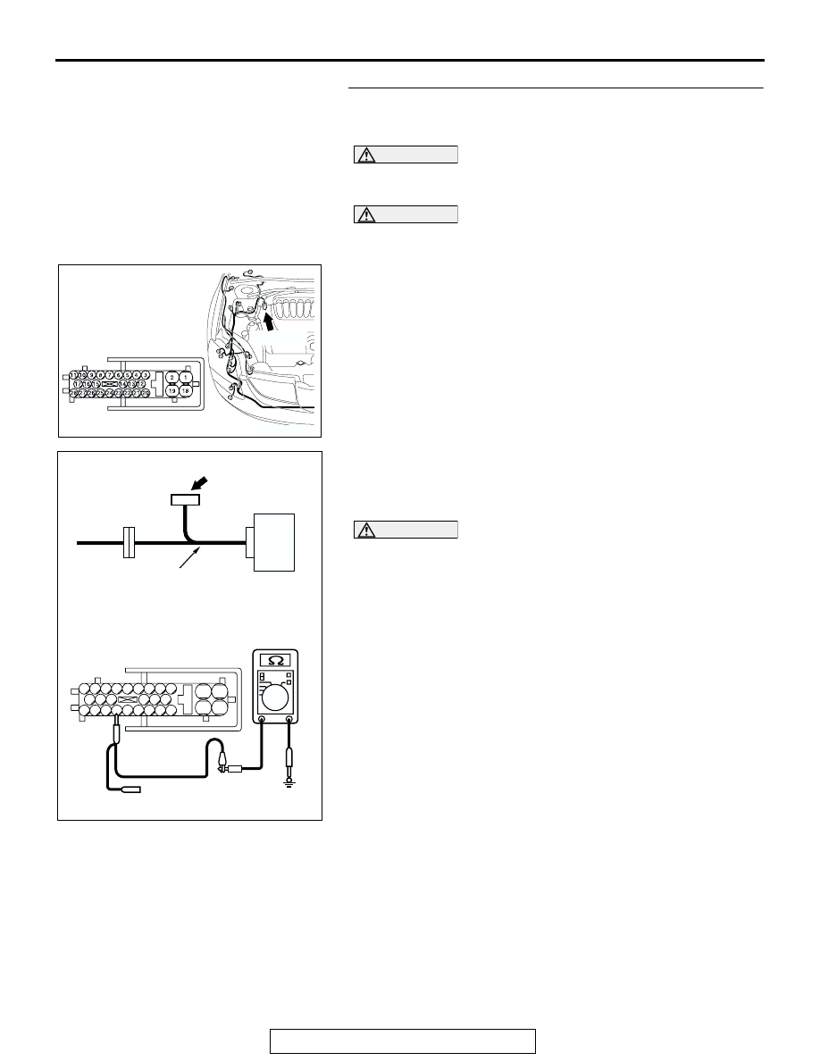
STEP 29. Check the CAN_H line inside the ABS-ECU for 
short to ground. Measure the resistance at ABS-ECU 

connector A-02.

CAUTION

A digital multimeter should be used. For details refer to 

P.54C-4

.

CAUTION

The test wiring harness should be used. For details refer to 

P.54C-4

.

(1) Disconnect ABS-ECU connector A-02.

(2) Connect special tool MB991970 (ABS check harness) to 

the ABS-ECU and the wiring harness, and measure the 
resistance at special tool MB991970 (ABS check harness).

(3) Turn the ignition switch to the "LOCK" (OFF) position.

CAUTION

Disconnect the negative battery terminal. For details refer 
to 

P.54C-4

.

(4) Disconnect the negative battery terminal.
(5) Measure the resistance between special tool MB991970 

(ABS check harness) connector terminal 25 and body 
ground.

OK: 1 k

 or more

Q: Does the resistance measure 1 k

 or more?

YES : If the resistance measures 1 k

Ω or more, diagnose 

CAN bus lines thoroughly by referring to 

P.54C-534

.

NO :  If the resistance measures less than 1 k

Ω, replace the 

ABS-ECU.

AC305206

CONNECTOR: A-02

AG

A-02 (GR)

HARNESS SIDE

AC209767

SPECIAL TOOL
MB991970

ABS-
ECU

SPECIAL TOOL MB991970 
CONNECTOR

AE

2

19

1

18

25

8

15

16

17

27

28

26

11

9

10

12

13

14

23

24

22 21

7

6

5

4

20

3

MEASUREMENT CONNECTOR

DIAGNOSIS

TSB Revision

CONTROLLER AREA NETWORK (CAN)

54C-292

STEP 30. Check intermediate connector C-29 for loose, 
corroded or damaged terminals, or terminals pushed back 
in the connector.

CAUTION

The strand end of the twisted wire should be within 10 cm 
(4 inches) from the connector. For details refer to 

P.54C-4

.

Q: Is intermediate connector C-29 in good condition?

YES : Go to Step 31.
NO :  Repair the damaged parts.

STEP 31. Check the CAN_L-side bus line (communication 
line including ECUs) of the front wiring harness for short 
to ground. Measure the resistance at intermediate 

connector C-29.

CAUTION

A digital multimeter should be used. For details refer to 

P.54C-4

.

CAUTION

The test wiring harness should be used. For details refer to 

P.54C-4

.

(1) Disconnect intermediate connector C-29, and measure the 

resistance at the male side (at front wiring harness side).

(2) Turn the ignition switch to the "LOCK" (OFF) position.

CAUTION

Disconnect the negative battery terminal. For details refer 
to 

P.54C-4

.

(3) Disconnect the negative battery terminal.

(4) Measure the resistance between intermediate connector 

terminal 12 and body ground.

OK: 1 k

 or more

Q: Does the resistance measure 1 k

 or more?

YES : If the resistance measures 1 k

Ω or more, go to Step 

32   .

NO :  If the resistance measures less than 1 k

Ω, go to Step 

52 .

AC305231AI

CONNECTOR: C-29

AC305231AI

CONNECTOR: C-29

AC209364

2 3

27

32

28

33

16

15

4 5

19

18

29

17

34

7 8

35

22

21

9 10

30

36

31

37

25

24

23

6

20

1

14

26

11

13

12

38

MALE SIDE: C-29

TEST HARNESS

GA

DIAGNOSIS

TSB Revision

CONTROLLER AREA NETWORK (CAN)

54C-293

STEP 32. Check joint connector (3) C-02 for loose, 
corroded or damaged terminals, or terminals pushed back 
in the connector.

CAUTION

The strand end of the twisted wire should be within 10 cm 
(4 inches) from the connector. For details refer to 

P.54C-4

.

Check the joint connector at the wiring harness side for loose, 
corroded or damaged terminals, or terminals pushed back in 
the connector, and also check the short pin behind the connec-
tor for corrosion, deformation and delamination.
Q: Is joint connector (3) C-02 in good condition?

YES : Go to Step 33.
NO :  Repair the damaged parts. Replace the joint 

connector as necessary.

AC305231AP

CONNECTOR: C-02

AC209350

1

12

2

13

3

14

4

15

5

16

6

17

7

18

8

19

9

20

10

21

11

22

AB

SHORT PIN

DIAGNOSIS

TSB Revision

CONTROLLER AREA NETWORK (CAN)

54C-294

STEP 33. Check the CAN_L line (communication line 
including the combination meter) between joint connector 
(3) and the combination meter connector for short to 

ground. Measure the resistance at joint connector (3) C-02.

CAUTION

A digital multimeter should be used. For details refer to 

P.54C-4

.

CAUTION

The test wiring harness should be used. For details refer to 

P.54C-4

.

(1) Disconnect joint connector (3) C-02, and measure the 

resistance at the wiring harness side of joint connector (3) 
C-02.

(2) Turn the ignition switch to the "LOCK" (OFF) position.

CAUTION

Disconnect the negative battery terminal. For details refer 
to 

P.54C-4

.

(3) Disconnect the negative battery terminal.

(4) Measure the resistance between joint connector (3) 

terminal 15 and body ground.

OK: 1 k

 or more

Q: Does the resistance measure 1 k

 or more?

YES : If the resistance measures 1 k

Ω or more, go to Step 

35   .

NO :  If the resistance measures less than 1 k

Ω, go to Step 

34 .

AC305231AP

CONNECTOR: C-02

AC209364IG

11

22

10

21

9

20

8

19

7

18

6

17

5

16

4

15

3

14

2

13

1

12

HARNESS SIDE: C-02

TEST 
HARNESS


Content   ..  418  419  420  421   ..