Mitsubishi Galant (2004+). Manual - part 398


  Index      Mitsubishi     Mitsubishi Galant - service repair manual 2004 year


Search            


Content   ..  396  397  398  399   ..


Mitsubishi Galant (2004+). Manual - part 398


DIAGNOSIS

TSB Revision

CONTROLLER AREA NETWORK (CAN)

54C-203

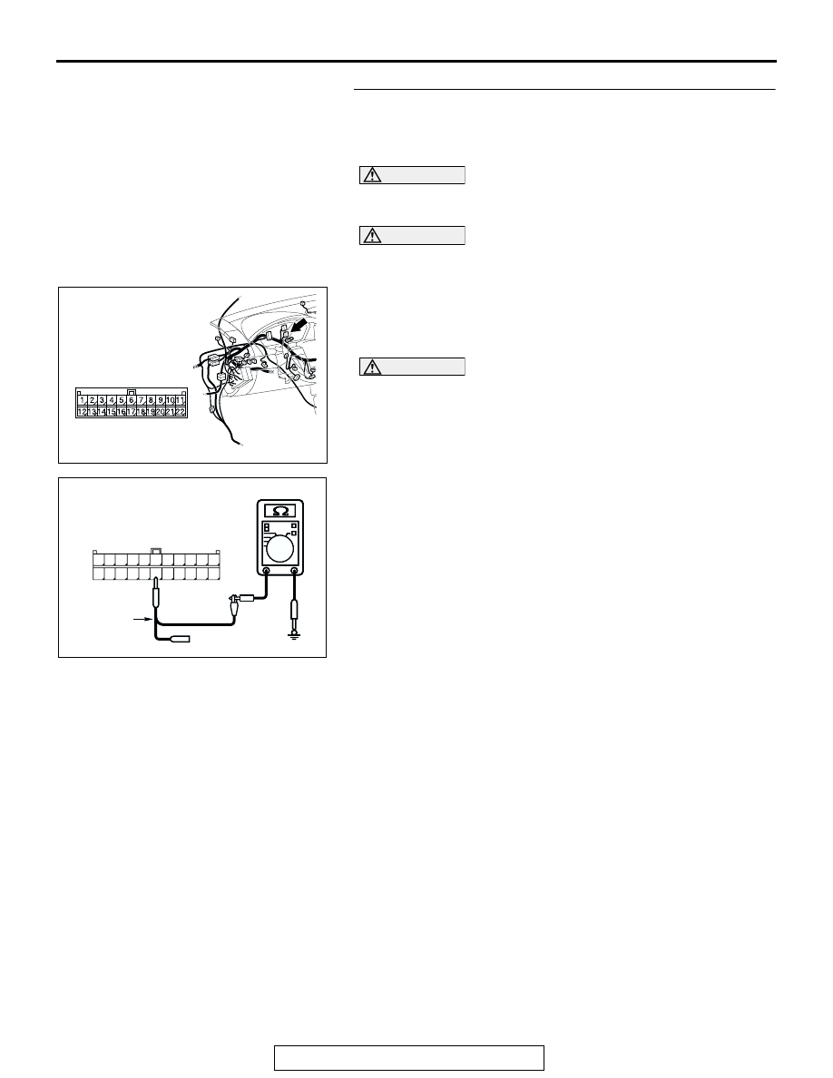
STEP 32. Check the CAN_L line (communication line 
including the A/C-ECU) between joint connector (3) and 
the A/C-ECU connector for short to ground. Measure the 

resistance at joint connector (3) C-02.

CAUTION

A digital multimeter should be used. For details refer to 

P.54C-4

.

CAUTION

The test wiring harness should be used. For details refer to 

P.54C-4

.

(1) Disconnect joint connector (3) C-02, and measure the 

resistance at the wiring harness side of joint connector (3) 
C-02.

(2) Turn the ignition switch to the "LOCK" (OFF) position.

CAUTION

Disconnect the negative battery terminal. For details refer 
to 

P.54C-4

.

(3) Disconnect the negative battery terminal.

(4) Measure the resistance between joint connector (3) 

terminal 17 and body ground.

OK: 1 k

 or more

Q: Does the resistance measure 1 k

 or more?

YES : If the resistance measures 1 k

Ω or more, go to Step 

35   .

NO :  If the resistance measures less than 1 k

Ω, go to Step 

33 .

AC305231AP

CONNECTOR: C-02

AC209364

11

22

10

21

9

20

8

19

7

18

6

17

5

16

4

15

3

14

2

13

1

12

AC209364

AC209364HY

HARNESS SIDE: C-02

TEST 
HARNESS

DIAGNOSIS

TSB Revision

CONTROLLER AREA NETWORK (CAN)

54C-204

STEP 33. Check A/C-ECU connector C-10 <manual air 
conditioning system (low)> or C-15 <manual air 
conditioning system (middle) or automatic air conditioning 
system> for loose, corroded or damaged terminals, or 
terminals pushed back in the connector.

CAUTION

The strand end of the twisted wire should be within 10 cm 
(4 inches) from the connector. For details refer to 

P.54C-4

.

Q: Is A/C-ECU connector C-10 <manual air conditioning 

system (low)> or C-15 <manual air conditioning system 
(middle) or automatic air conditioning system> in good 
condition?
YES : 
Go to Step 34.
NO :  Repair the damaged parts.

AC305234AB

C-10 HARNESS SIDE

C-15 HARNESS SIDE

CONNECTORS: C-10, C-15

C-10 (B)

C-15 (B)

DIAGNOSIS

TSB Revision

CONTROLLER AREA NETWORK (CAN)

54C-205

STEP 34. Check the CAN_L line (communication line only) 
between joint connector (3) and A/C-ECU connector for 
short to ground. Measure the resistance at joint connector 

(3) C-02.

CAUTION

A digital multimeter should be used. For details refer to 

P.54C-4

.

CAUTION

The test wiring harness should be used. For details refer to 

P.54C-4

.

(1) Disconnect joint connector (3) C-02 and A/C-ECU 

connector C-10 <manual air conditioning system (low)> or 
C-15 <manual air conditioning system (middle) or automatic 
air conditioning system>, and measure the resistance at the 
wiring harness side of joint connector (3) C-02.

(2) Turn the ignition switch to the "LOCK" (OFF) position.

CAUTION

Disconnect the negative battery terminal. For details refer 
to 

P.54C-4

.

(3) Disconnect the negative battery terminal.

AC305231AP

CONNECTOR: C-02

AC305234AB

C-10 HARNESS SIDE

C-15 HARNESS SIDE

CONNECTORS: C-10, C-15

C-10 (B)

C-15 (B)

DIAGNOSIS

TSB Revision

CONTROLLER AREA NETWORK (CAN)

54C-206

(4) Measure the resistance between joint connector (3) 

terminal 17 and body ground.

OK: 1 k

 or more

CAUTION

Strictly observe the specified wiring harness repair proce-
dure. For details refer to 

P.54C-5

.

Q: Does the resistance measure 1 k

 or more?

YES : If the resistance measures 1 k

Ω or more, diagnose 

CAN bus lines thoroughly by referring to 

P.54C-465

.

NO :  If the resistance measures less than 1 k

Ω, repair the 

wiring harness between joint connector (3) and the 
A/C-ECU connector.

STEP 35. Check the CAN_L line (communication line 
including the SRS-ECU) between joint connector (3) and 
the SRS-ECU connector for short to ground. Measure the 

resistance at joint connector (3) C-02.

CAUTION

A digital multimeter should be used. For details refer to 

P.54C-4

.

CAUTION

The test wiring harness should be used. For details refer to 

P.54C-4

.

(1) Disconnect joint connector (3) C-02, and measure the 

resistance at the wiring harness side of joint connector (3) 

C-02.

(2) Turn the ignition switch to the "LOCK" (OFF) position.

CAUTION

Disconnect the negative battery terminal. For details refer 
to 

P.54C-4

.

(3) Disconnect the negative battery terminal.

(4) Measure the resistance between joint connector (3) 

terminals 14 and body ground.

OK: 1 k

 or more

Q: Does the resistance measure 1 k

 or more?

YES : If the resistance measures 1 k

Ω or more, go to Step 

41   .

NO :  If the resistance measures less than 1 k

Ω, go to Step 

36.

AC209364

11

22

10

21

9

20

8

19

7

18

6

17

5

16

4

15

3

14

2

13

1

12

AC209364

AC209364HY

HARNESS SIDE: C-02

TEST 
HARNESS

AC305231AP

CONNECTOR: C-02

AC209364IK

11

22

10

21

9

20

8

19

7

18

6

17

5

16

4

15

3

14

2

13

1

12

HARNESS SIDE: C-02

TEST 
HARNESS


Content   ..  396  397  398  399   ..