Mitsubishi Galant (2004+). Manual - part 374
DIAGNOSIS
TSB Revision
CONTROLLER AREA NETWORK (CAN)
54C-107
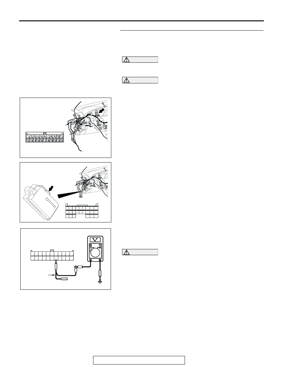
STEP 34. Check the CAN_L line (communication line only)
between joint connector (3) and ETACS-ECU connector for
a short to the power supply. Measure the voltage at joint
connector (3) C-02.
CAUTION
A digital multimeter should be used. For details refer to
CAUTION
The test wiring harness should be used. For details refer to
(1) Disconnect joint connector (3) C-02 and ETACS-ECU
connector C-218, and measure the voltage at the wiring
harness side of joint connector (3) C-02.
(2) Turn the ignition switch to the "ON" position.
(3) Measure the voltage between joint connector (3) terminal
16 and body ground.
OK: 1.0 V or less
CAUTION
Strictly observe the specified wiring harness repair proce-
dure. For details refer to
Q: Does the voltage measure 1.0 V or less?
YES : If the voltage measures 1.0 V or less, diagnose CAN
bus lines thoroughly by referring to
NO : If the voltage measures more than 1.0 V, repair the
wiring harness between joint connector (3) and the
ETACS-ECU connector.
AC305231AP
CONNECTOR: C-02
AC305413
C-218 (GR)
CONNECTOR: C-218
AI
HARNESS SIDE
JUNCTION BLOCK
(REAR VIEW)
68
74
63
66
72
73
67
65 64
61
70
71
62
69
60
57
58
59
56 55
52
54 53
51
AC209365
11
22
10
21
9
20
8
19
7
18
6
17
5
16
4
15
3
14
2
13
1
12
AC209365
AC209365GC
HARNESS SIDE: C-02
TEST
HARNESS