Mitsubishi Galant (2004+). Manual - part 319
SYMPTOM PROCEDURES
TSB Revision
SIMPLIFIED WIRING SYSTEM (SWS)
54B-467
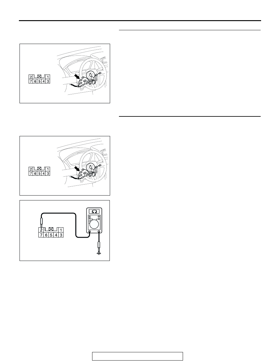
STEP 8. Check the key reminder switch (ignition key hole
illumination).
(1) Disconnect key reminder switch connector C-310.
(2) Remove the ignition key hole illumination light bulb. Then
measure the resistance value between the bulb terminals.
(3) Install a bulb to the key remainder switch, and measure the
resistance between connector C-310 terminals 1 and 2. The
measured resistance value should be roughly the same as
the value measured in Step (2).
Q: Are these two resistance values extremely different?
YES : Replace the key reminder switch. Verify that the
ignition key hole illumination light illuminates normally.
NO : <Nearly equal> Go to Step 9.
STEP 9. Check the battery power supply circuit to the key
reminder switch circuit. Measure the voltage at key
reminder switch connector C-310.
(1) Disconnect key reminder switch connector C-310, and
measure the voltage available at the wiring harness side of
the connector.
(2) Measure the voltage between terminal 2 and ground.
• The voltage should measure approximately 12 volts
(battery positive voltage).
Q: Is the measured voltage approximately 12 volts (battery
positive voltage)?
YES : Go to Step 11.
NO : Go to Step 10.
AC305235AF
CONNECTOR: C-310
HARNESS SIDE
AC305235AF
CONNECTOR: C-310
HARNESS SIDE
AC209364
CONNECTOR C-310
(HARNESS SIDE)
GY