Mitsubishi Galant (2004+). Manual - part 316


  Index      Mitsubishi     Mitsubishi Galant - service repair manual 2004 year


Search            


Content   ..  314  315  316  317   ..


Mitsubishi Galant (2004+). Manual - part 316


SYMPTOM PROCEDURES

TSB Revision

SIMPLIFIED WIRING SYSTEM (SWS)

54B-455

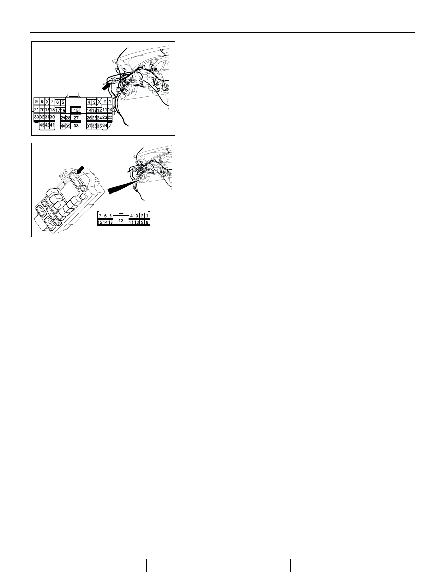
NOTE: Also check intermediate connector C-28 and junction 
block connector C-204 for loose, corroded, or damaged termi-
nals, or terminals pushed back in the connector. If intermediate 
connector C-28 or junction block connector C-204 is damaged, 
repair or replace the damaged component(s) as described in 
GROUP 00E, Harness Connector Inspection 

P.00E-2

.

Q: Is the wiring harness between trunk light connector 

D-10 (terminals 1 and 2) and ETACS-ECU connector 
C-219 (terminal 6) or C-218 (terminal 52) in good 
condition?
YES : 
Replace the trunk light. Check that the trunk light 

illuminates normally.

NO :  The wiring harness may be damaged or the 

connector(s) may have loose, corroded or damaged 
terminals, or terminals pushed back in the connector. 
Repair the wiring harness as necessary. Check that 
the trunk light illuminates normally.

AC305231AE

CONNECTOR:C-28

AC305415AJ

CONNECTOR: C-204

HARNESS SIDE

JUNCTION BLOCK

(FRONT VIEW)

SYMPTOM PROCEDURES

TSB Revision

SIMPLIFIED WIRING SYSTEM (SWS)

54B-456

INSPECTION PROCEDURE K-3: Interior light: Dome light dimming function does not work normally.

NOTE: This troubleshooting procedure requires the 
use of scan tool MB991958 and SWS monitor kit 
MB991813. For details on how to use the SWS mon-
itor, refer to "How to use SWS monitor 

P.54B-15

."

.

CIRCUIT OPERATION
The ETACS-ECU operates the dome light dimming 
function according to the input signals from the fol-
lowing switches:

• Ignition switch (IG1): OFF

• Key reminder switch: ON

• Door switches: OFF

• Driver's door lock actuator switch: LOCK or 

UNLOCK

.

TECHNICAL DESCRIPTION (COMMENT)
If the dome lights do not dim normally, the input cir-
cuits from the switches described in "CIRCUIT 
OPERATION" or the ETACS-ECU may be defective.

.

TROUBLESHOOTING HINTS

• Trouble in input signal system

• The wiring harness or connectors may have 

loose, corroded, or damaged terminals, or termi-
nals pushed back in the connector

• The ETACS-ECU may be defective

ETACS-
ECU

· 

ALL DOOR 

SWITCH

· 

FRONT 

DOOR SWITCH

· IGNITION SWITCH (IG1)
· 

INTERIOR LIGHT 

  LOADED SIGNAL
· KEY REMINDER SWITCH

JUNCTION BLOCK SIDE

JUNCTION 
BLOCK

INPUT SIGNAL

NOTE

WITHOUT SUNROOF
WITH SUNROOF

· 

MAP LIGHT ASSEMBLY

· OVERHEAD CONSOLE 

 ASSEMBLY

· 

REAR DOME LIGHT

· 

TRUNK LIGHT

Ignition Dimming Function

SYMPTOM PROCEDURES

TSB Revision

SIMPLIFIED WIRING SYSTEM (SWS)

54B-457

DIAGNOSIS

Required Special Tools:

• MB991223: Harness Set

• MB991958: Scan Tool (MUT-III Sub Assembly)

• MB991824: Vehicle Communication Interface (V.C.I.)

• MB991827: MUT-III USB Cable

• MB991910: MUT-III Main Harness A

• MB991813: SWS Monitor Kit

• MB991806: SWS Monitor Cartridge

• MB991812: SWS Monitor Harness (For Column-ECU)

• MB991822: Probe Harness

STEP 1. Check the dome light.

If a door is opened while the dome light switch is at 
"door-linked" position, the dome light should illuminate.
Q: Does the dome light illuminate normally?

YES : Go to Step 2.
NO :  Refer to Inspection Procedure K-1 "The dome light do 

not illuminate and go out normally 

P.54B-433

."

STEP 2. Check the adjustment function.
Q: Has the dome light delay-off time been set to other than 

"0 second" by the adjustment function?
YES : 
Go to Step 3.
NO :  Set the dome light delay-off time to "0 second."

SYMPTOM PROCEDURES

TSB Revision

SIMPLIFIED WIRING SYSTEM (SWS)

54B-458

STEP 3. Use scan tool MB991958 to select "ECU COMM 
Check" on the SWS monitor display.

Check the ETACS-ECU.

CAUTION

To prevent damage to scan tool MB991958, always turn the 
ignition switch to the "LOCK" (OFF) position before con-
necting or disconnecting scan tool MB991958. Connect 
special tool MB991910 before connecting special tool 
MB991812. Be sure to connect special tool MB991806 after 
turning on special tool MB991824.
(1) Connect the special tool. Refer to "How to connect SWS 

monitor 

P.54B-13

."

(2) Turn the ignition switch to the "LOCK" (OFF) position.
(3) Operate scan tool MB991958 according to the procedure 

below to display "ECU COMM Check."
a. Select "Interactive Diagnosis."
b. Select "System select."
c. Select "SWS."
d. Select "SWS MONITOR."
e. Select "ECU COMM Check."

(4) Scan tool MB991958 should show "OK" on the "ECU 

COMM Check" menu for the "ETACS ECU" menu.

Q: Is "OK" displayed for the "ETACS ECU" menu?

YES : Go to Step 4.
NO :  Refer to Inspection Procedure A-3 "Communication 

with the ETACS-ECU is not possible 

P.54B-79

."

AC305411AB

MB991910

DATA LINK

CONNECTOR

MB991827

MB991824

MB991806

MB991812

AC302210

COLUMN SWITCH 
CONNECTOR

COLUMN SWITCH 
CONNECTOR AT 
HARNESS SIDE 

MB991812

AB


Content   ..  314  315  316  317   ..