Mitsubishi Galant (2004+). Manual - part 306


  Index      Mitsubishi     Mitsubishi Galant - service repair manual 2004 year


Search            


Content   ..  304  305  306  307   ..


Mitsubishi Galant (2004+). Manual - part 306


SYMPTOM PROCEDURES

TSB Revision

SIMPLIFIED WIRING SYSTEM (SWS)

54B-415

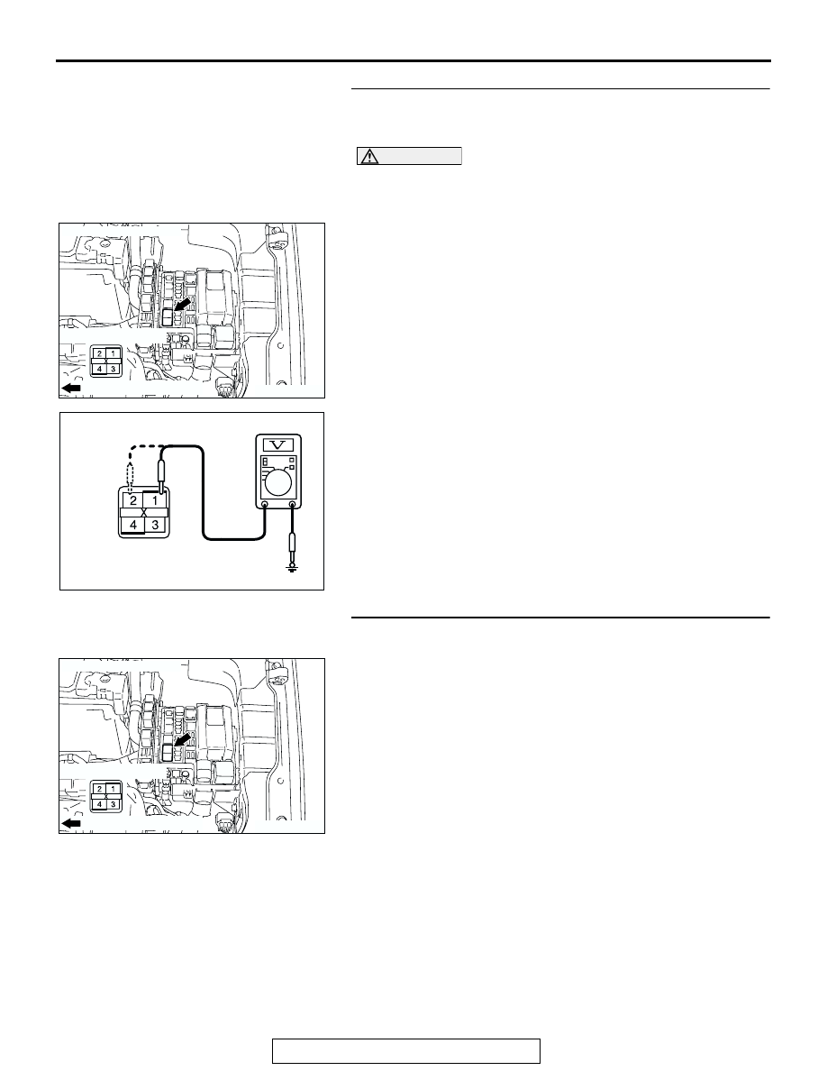
STEP 5. Check the battery power supply circuit to the fog 
light relay. Measure the voltage at fog light relay connector 
A-05X.

CAUTION

The top and bottom of the fog light relay are difficult to 
identify. Prior to inspection, confirm the triangle mark on 
the relay box.
(1) Disconnect fog light relay connector A-05X and measure 

the voltage available at the relay box side of the connector.

(2) Measure the voltage between terminal 1 and ground, and 

also between terminal 2 and ground.

• The voltage should measure approximately 12 volts 

(battery positive voltage).

Q: Is the measured voltage approximately 12 volts (battery 

positive voltage)?
YES : 
Go to Step 7.
NO :  Go to Step 6.

STEP 6. Check the wiring harness between fog light relay 
connector A-05X (terminals 1 and 2) and the battery.

Q: Is the wiring harness between fog light relay connector 

A-05X (terminals 1 and 2) and the battery in good 
condition?
YES : 
No action is necessary and testing is complete.
NO :  The wiring harness may be damaged or the 

connector(s) may have loose, corroded or damaged 
terminals, or terminals pushed back in the connector. 
Repair the wiring harness as necessary. Verify that 
the fog lights illuminate normally.

AC305979 AB

CONNECTOR: A-05X

RELAY BOX SIDE

FRONT OF VEHICLE

AC209365

CONNECTOR A-05X
(RELAY BOX SIDE)

EK

AC305979 AB

CONNECTOR: A-05X

RELAY BOX SIDE

FRONT OF VEHICLE

SYMPTOM PROCEDURES

TSB Revision

SIMPLIFIED WIRING SYSTEM (SWS)

54B-416

STEP 7. Check front-ECU connector A-11X for loose, 
corroded or damaged terminals, or terminals pushed back 
in the connector.

Q: Is front-ECU connector A-11X in good condition?

YES : Go to Step 8.
NO :  Repair or replace the damaged component(s). Refer 

to GROUP 00E, Harness Connector Inspection 

P.00E-2

. Verify that the fog lights illuminate normally.

STEP 8. Check the wiring harness between fog light relay 
connector A-05X (terminal 3) and front-ECU connector 
A-11X (terminal 11).

Q: Is the wiring harness between fog light relay connector 

A-05X (terminal 3) and front-ECU connector A-11X 
(terminal 11) in good condition?
YES : 
Go to Step 9.
NO :  The wiring harness may be damaged or the 

connector(s) may have loose, corroded or damaged 
terminals, or terminals pushed back in the connector. 
Repair the wiring harness as necessary. Verify that 
the fog lights illuminate normally.

STEP 9. Replace the ECU.
(1) Replace the front-ECU.
(2) The fog lights should illuminate normally.
Q: Do the fog lights illuminate normally?

YES : No action is necessary and testing is complete.
NO :  Replace the ETACS-ECU. Verify that the fog lights 

illuminate normally.

AC305979 AB

CONNECTOR: A-05X

RELAY BOX SIDE

FRONT OF VEHICLE

AC305987AB

CONNECTORS: A-05X, A-11X

RELAY BOX SIDE

A-11X

A-05X

A-05X

A-11X

FRONT OF VEHICLE

RELAY BOX SIDE

SYMPTOM PROCEDURES

TSB Revision

SIMPLIFIED WIRING SYSTEM (SWS)

54B-417

INSPECTION PROCEDURE J-2: Fog Light: Fog lights do not go out when the headlights (low-beam) 
are turned off while the fog lights are on.

.

TECHNICAL DESCRIPTION (COMMENT)
If the trouble above occurs, the front-ECU may be 
defective.

.

TROUBLESHOOTING HINT
The front-ECU may be defective

DIAGNOSIS

Replace the front-ECU.
The fog lights should go out when the headlights (low-beam) 
are turned off while the fog lights are on.

INSPECTION PROCEDURE J-3: Fog Light: One of the fog lights does not illuminate.

BATTERY

FOG
LIGHT
(RH)

FOG
LIGHT
(LH)

FRONT-ECU

RELAY
BOX

FOG LIGHT
RELAY

Fog Light Circuit

SYMPTOM PROCEDURES

TSB Revision

SIMPLIFIED WIRING SYSTEM (SWS)

54B-418

.

TECHNICAL DESCRIPTION (COMMENT)
If one of the fog lights does not illuminate, the fog 
light relay or the fog light bulb may be defective. If 
the fog light indicator light does not illuminate, the 
combination meter may be defective.

.

TROUBLESHOOTING HINTS

• The wiring harness or connectors may have 

loose, corroded, or damaged terminals, or termi-
nals pushed back in the connector

• The fog light bulb may be defective

.

DIAGNOSIS

Required Special Tool:

• MB991223: Harness Set

STEP 1. Verify that the fog lights and the fog light indicator 
light illuminate.
Q: Do the fog lights and the fog light indicator light 

illuminate normally?
Only the fog light (LH) does not illuminate : 
Go to Step 2.
Only the fog light (RH) does not illuminate : Go to Step 

8.

Only the fog light indicator does not illuminate : Refer to 

Inspection Procedure J-4 "The fog light indicator does 
not illuminate normally 

P.54B-423

."

Both of the fog lights do not illuminate : Refer to 

Inspection Procedure J-1 "Fog lights do not illuminate 
when the fog light switch is turned on 

P.54B-411

."

AC305979

CONNECTOR: A-05X

AC

AC305210AB

CONNECTOR: A-22

A-22 (B)

AC305206

CONNECTOTR: A-28

AB

A-28 (B)


Content   ..  304  305  306  307   ..