Mitsubishi Galant (2004+). Manual - part 264


  Index      Mitsubishi     Mitsubishi Galant - service repair manual 2004 year


Search            


Content   ..  262  263  264  265   ..


Mitsubishi Galant (2004+). Manual - part 264


SYMPTOM PROCEDURES

TSB Revision

SIMPLIFIED WIRING SYSTEM (SWS)

54B-247

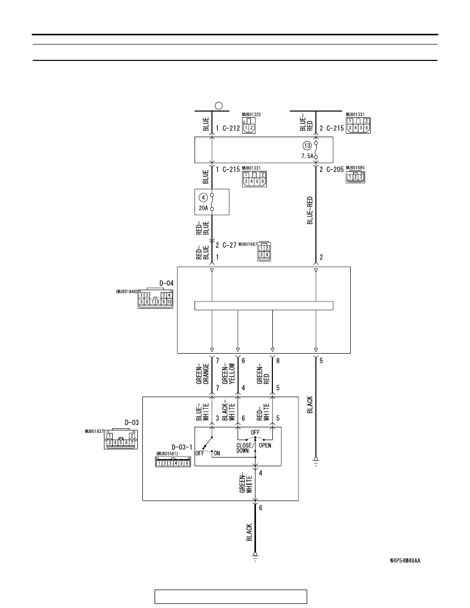
INSPECTION PROCEDURE F-1: Sunroof: Sunroof does not operate.

SUNROOF-ECU

SUNROOF
SWITCH

OVERHEAD
CONSOLE
ASSEMBLY

SUNROOF MOTOR
ASSEMBLY

IGNITION
SWITCH (IG2)

FUSIBLE
LINK

5

JUNCTION 
BLOCK

JUNCTION 
BLOCK

Sunroof Motor Assembly Power Supply Circuit

SYMPTOM PROCEDURES

TSB Revision

SIMPLIFIED WIRING SYSTEM (SWS)

54B-248

.

CIRCUIT OPERATION

• The sunroof motor assembly is energized 

through fusible link (5) by the battery.

• When the ignition switch (IG2) signal is on, the 

sunroof motor assembly is ready to operate.

.

TROUBLESHOOTING HINTS

• The sunroof switch may be defective

• The sunroof motor assembly may be defective

• The wiring harness or connectors may have 

loose, corroded, or damaged terminals, or termi-
nals pushed back in the connector

AC305015

AC305015AF

FUSIBLE LINK (5)

AC305231

AC305231BW

CONNECTORS: C-27

AC305415

AC305415

C-212

C-215

C-205

AX

JUNCTION BLOCK

(FRONT VIEW)

CONNECTORS: C-205, C-212, C-215

AC305264

AC305264

AO

CONNECTOR: D-03, D-04

D-04

D-03

AC307976

OVERHEAD CONSOLE
ASSEMBLY

CONNECTOR: D-03-1

AC

SYMPTOM PROCEDURES

TSB Revision

SIMPLIFIED WIRING SYSTEM (SWS)

54B-249

DIAGNOSIS

Required Special Tool:

• MB991223: Test Harness Set

STEP 1. Check sunroof motor assembly connector D-04 
for loose, corroded or damaged terminals, or terminals 
pushed back in the connector.

Q: Is sunroof motor assembly connector D-04 in good 

condition?
YES : 
Go to Step 2.
NO :  Repair or replace the damaged component(s). Refer 

to GROUP 00E, Harness Connector Inspection 

P.00E-2

. Check that the sunroof works normally.

STEP 2. Check the fusible link (5) line of power supply 
circuit to the sunroof motor assembly. Measure the voltage 
at sunroof motor assembly connector D-04.

(1) Disconnect sunroof motor assembly connector D-04 and 

measure the voltage available at the wiring harness side of 

the connector.

(2) Measure the voltage between terminal 1 and ground.

• The voltage should measure approximately 12 volts 

(battery positive voltage).

Q: Is the measured voltage approximately 12 volts (battery 

positive voltage)?
YES : 
Go to Step 4.
NO :  Go to Step 3.

AC305264

AC305264

AM

CONNECTOR: D-04

HARNESS SIDE

AC305264

AC305264

AM

CONNECTOR: D-04

HARNESS SIDE

AC209365 FG

CONNECTOR D-04
(HARNESS SIDE)

SYMPTOM PROCEDURES

TSB Revision

SIMPLIFIED WIRING SYSTEM (SWS)

54B-250

STEP 3. Check the wiring harness between sunroof motor 
assembly connector D-04 (terminal 1) and fusible link (5).

AC305015

AC305015AF

FUSIBLE LINK (5)

AC305264

AC305264

AM

CONNECTOR: D-04

HARNESS SIDE


Content   ..  262  263  264  265   ..