Mitsubishi Galant (2004+). Manual - part 247
SYMPTOM PROCEDURES
TSB Revision
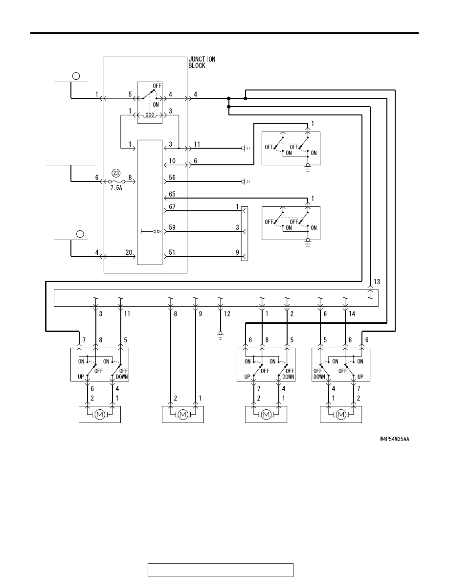
SIMPLIFIED WIRING SYSTEM (SWS)
54B-179
IGNITION
SWITCH (IG1)
ETACS-
ECU
POWER
WINDOW
RELAY
FUSIBLE
LINK
5
RELAY
BOX
(FUSE )
FRONT
DOOR
SWITCH
(LH)
FRONT
DOOR
SWITCH
(RH)
FRONT
POWER
WINDOW
SUB
SWITCH
(RH)
FRONT DOOR WINDOW
REGULATOR MOTOR
(LH)
FRONT DOOR WINDOW
REGULATOR MOTOR
(RH)
REAR DOOR WINDOW
REGULATOR MOTOR
(LH)
REAR DOOR WINDOW
REGULATOR MOTOR
(RH)
REAR
POWER
WINDOW
SUB
SWITCH
(LH)
REAR
POWER
WINDOW
SUB
SWITCH
(RH)
DATA LINK
CONNECTOR
POWER WINDOW MAIN SWITCH
22