Mitsubishi Galant (2004+). Manual - part 235


  Index      Mitsubishi     Mitsubishi Galant - service repair manual 2004 year


Search            


Content   ..  233  234  235  236   ..


Mitsubishi Galant (2004+). Manual - part 235


SYMPTOM PROCEDURES

TSB Revision

SIMPLIFIED WIRING SYSTEM (SWS)

54B-131

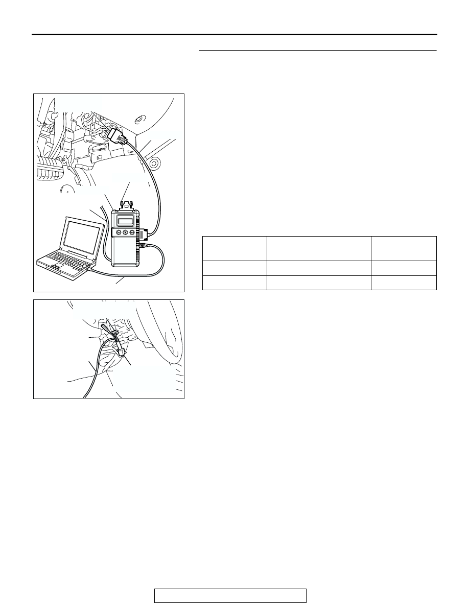
STEP 5. Check the input signal by using "FUNCTION 
DIAG." menu of the SWS monitor.

Turn the ignition switch to the "ON" position to check the input 
signals from the following switches.
(1) Operate scan tool MB991958 according to the procedure 

below to display "OTHER ALARM."
a. Select "Interactive Diagnosis."
b. Select "System Select."
c. Select "SWS."
d. Select "SWS MONITOR."
e. Select "Function Diag."
f. Select "BUZZER."
g. Select "OTHER ALARM."

(2) Check that normal conditions are displayed for the items 

described in the table below.
NOTE: If the function switch of the multi center display (mid-
dle-grade type) is operated, check that No.43 "BUZZER" is 
displayed as normal condition.

Q: Are normal conditions displayed for the "IG SW (IG1)" 

and "BUZZER"?
Normal conditions are displayed for all the items : 

Replace the ETACS-ECU. Verify that the multi center 
display operating sound function works normally.

Normal condition is not displayed for "IG SW (IG1)" : 

Refer to Inspection Procedure M-2 "ETACS-ECU 
does not receive any signal from the ignition switch 
(IG1) 

P.54B-490

."

Normal condition is not displayed for "BUZZER" : 

Replace the ETACS-ECU. Verify that the multi center 
display operating sound function works normally.

ITEM NO.

ITEM NAME

NORMAL 
CONDITION

ITEM 30

IG SW (IG1)

ON

ITEM 43

BUZZER

ON

AC305411AB

MB991910

DATA LINK

CONNECTOR

MB991827

MB991824

MB991806

MB991812

AC302210

COLUMN SWITCH 
CONNECTOR

COLUMN SWITCH 
CONNECTOR AT 
HARNESS SIDE 

MB991812

AB

SYMPTOM PROCEDURES

TSB Revision

SIMPLIFIED WIRING SYSTEM (SWS)

54B-132

INSPECTION PROCEDURE B-6: Tone Alarm: Turn-signal Light Buzzer Function does not Work 
Normally.

NOTE: This troubleshooting procedure requires use 
of scan tool MB991958 and SWS monitor kit 
MB991813. For details on how to use the SWS mon-
itor, refer to "How to use SWS monitor 

P.54B-15

."

.

CIRCUIT OPERATION
The ETACS-ECU controls the turn-signal light buzzer 
function, based on the switch signals below:

• Turn-signal light switch: ON

• Hazard switch: ON

.

TECHNICAL DESCRIPTION (COMMENT)
If the turn-signal light buzzer function does not work 
normally, connector(s), wiring harness, the column 
switch, the ETACS-ECU or the input signal circuit 
may be defective.

.

TROUBLESHOOTING HINTS

• Trouble in input signal system

• The wiring harness or connectors may have 

loose, corroded, or damaged terminals, or termi-
nals pushed back in the connector

• The ETACS-ECU may be defective

ETACS-
ECU

· 

HAZARD WARNING LIGHT

 SWITCH

· 

TURN-SIGNAL LIGHT

 SWITCH

Turn-signal Annunciation Function

SYMPTOM PROCEDURES

TSB Revision

SIMPLIFIED WIRING SYSTEM (SWS)

54B-133

DIAGNOSIS

Required Special Tools:

• MB991223: Harness Set

• MB991958: Scan Tool (MUT-III Sub Assembly)

• MB991824: Vehicle Communication Interface (V.C.I.)

• MB991827: MUT-III USB Cable

• MB991910: MUT-III Main Harness A

• MB991813: SWS Monitor Kit

• MB991806: SWS Monitor Cartridge

• MB991812: SWS Monitor Harness (For Column-ECU)

• MB991822: Probe Harness

STEP 1. Check the adjustment function.
Q: Has the turn-signal light buzzer function been enabled 

by the adjustment function?
YES : 
Go to Step 2.
NO :  Enable the turn-signal light buzzer function.

STEP 2. Check whether the turn-signal lights illuminate.

When the turn-signal light switch or the hazard warning light 
switch is operated, check that the turn-signal lights flash.
Q: Are the turn-signal lights in good condition?

YES : Go to Step 3.
NO :  First, repair the turn-signal light(s). Refer to Inspection 

Procedure I-3 "One of the turn-signal lights does not 
illuminate 

P.54B-390

."

SYMPTOM PROCEDURES

TSB Revision

SIMPLIFIED WIRING SYSTEM (SWS)

54B-134

STEP 3. Use scan tool MB991958 to select "ECU COMM 
Check" on the SWS monitor display.

Check the following ECUs:

• ETACS-ECU

• Column-ECU

CAUTION

To prevent damage to scan tool MB991958, always turn the 
ignition switch to the "LOCK" (OFF) position before con-
necting or disconnecting scan tool MB991958. Connect 
special tool MB991910 before connecting special tool 
MB991812. Be sure to connect special tool MB991806 after 
turning on special tool MB991824.
(1) Connect the special tool. Refer to "How to connect SWS 

monitor 

P.54B-13

."

(2) Turn the ignition switch to the "ON" position.
(3) Operate scan tool MB991958 according to the procedure 

below to display "ECU COMM Check."

1. Select "Interactive Diagnosis."
2. Select "System Select."
3. Select "SWS."
4. Select "SWS MONITOR."
5. Select "ECU COMM Check."

(4) Scan tool MB991958 should show "OK" on the "ECU 

COMM Check" menus for both the "ETACS ECU" and the 
"COLUMN ECU" menus.

Q: Is "OK" displayed for both the "ETACS ECU" and 

"COLUMN ECU" menus?
"OK" is displayed for all the items : 
Go to Step 4.
"NG" is displayed for the "COLUMN ECU" menu : Refer 

to Inspection Procedure A-2 "Communication with the 
column switch (column-ECU) is not possible 

P.54B-72

."

"NG" is displayed for the "ETACS ECU" menu : Refer to 

Inspection Procedure A-3 "Communication with the 
ETACS-ECU is not possible 

P.54B-79

."

"NG" is displayed for all the items : Refer to Inspection 

Procedure A-3 "Communication with the ETACS-ECU 
is not possible 

P.54B-79

."

AC305411AB

MB991910

DATA LINK

CONNECTOR

MB991827

MB991824

MB991806

MB991812

AC302210

COLUMN SWITCH 
CONNECTOR

COLUMN SWITCH 
CONNECTOR AT 
HARNESS SIDE 

MB991812

AB


Content   ..  233  234  235  236   ..