Mitsubishi Galant (2004+). Manual - part 232


  Index      Mitsubishi     Mitsubishi Galant - service repair manual 2004 year


Search            


Content   ..  230  231  232  233   ..


Mitsubishi Galant (2004+). Manual - part 232


SYMPTOM PROCEDURES

TSB Revision

SIMPLIFIED WIRING SYSTEM (SWS)

54B-119

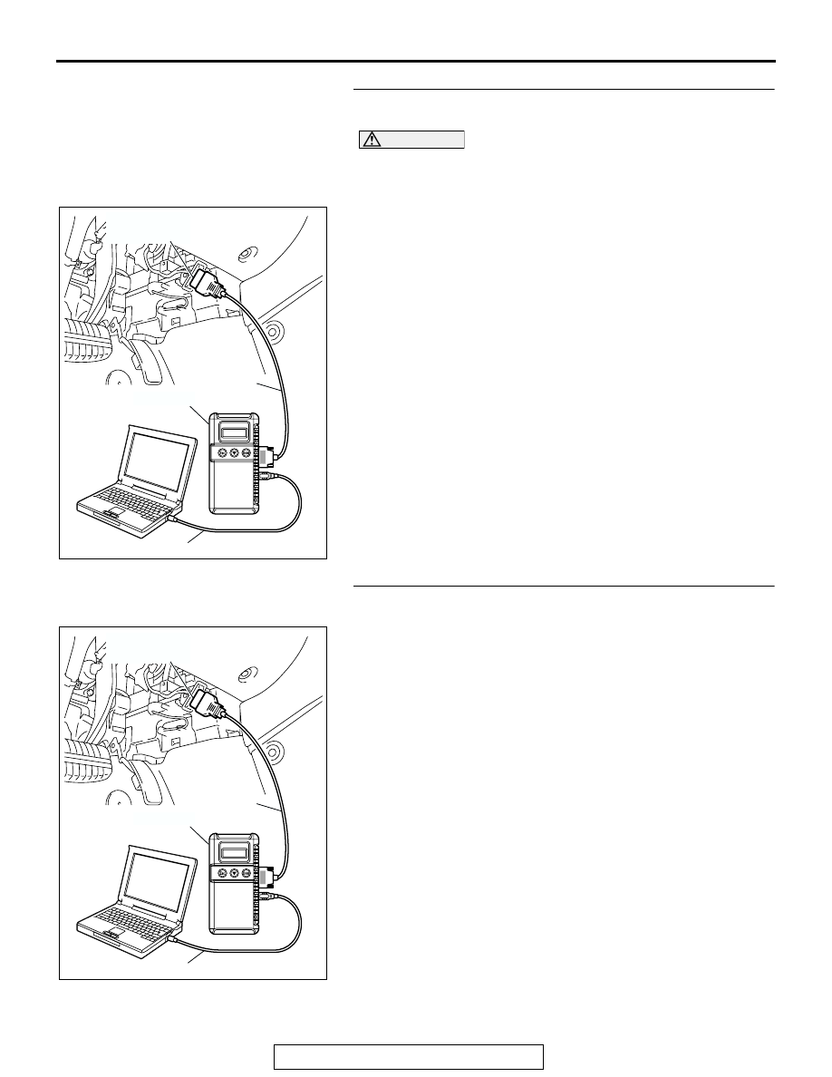
STEP 1. Using scan tool MB991958, diagnose the CAN bus 
line.

CAUTION

To prevent damage to scan tool MB991958, always turn the 
ignition switch to the "LOCK" (OFF) position before con-
necting or disconnecting scan tool MB991958.
(1) Connect scan tool MB991958. Refer to "How to connect 

SWS monitor 

P.54B-13

."

(2) Turn the ignition switch to the "ON" position.
(3) Diagnose the CAN bus line.
(4) Turn the ignition switch to the "LOCK" (OFF) position.
Q: Is the CAN bus line found to be normal?

YES : Go to Step 2.
NO :  Repair the CAN bus line (Refer to GROUP 54C, 

Diagnosis 

P.54C-14

).

STEP 2. Using scan tool MB991958, read the diagnostic 
trouble code related to the combination meter.

Check whether the combination meter-related DTC is set.
(1) Turn the ignition switch to the "ON" position.
(2) Check whether the combination meter-related DTC is set.

(3) Turn the ignition switch to the "LOCK" (OFF) position.
Q: Is the DTC set?

YES : Diagnose the multi center display unit (middle-grade 

type) (Refer to GROUP 54A, Diagnosis 

P.54A-237

).

NO :  Go to Step 3.

AC305412

AB

MB991910

DATA LINK

CONNECTOR

MB991824

MB991827

AC305412

AB

MB991910

DATA LINK

CONNECTOR

MB991824

MB991827

SYMPTOM PROCEDURES

TSB Revision

SIMPLIFIED WIRING SYSTEM (SWS)

54B-120

STEP 3. Use scan tool MB991958 to select "ECU COMM 
Check" on the SWS monitor display.

Check the ETACS-ECU.

CAUTION

Connect special tool MB991910 before connecting special 
tool MB991812. Be sure to connect special tool MB991806 
after turning on special tool MB991824.
(1) Connect the SWS monitor. Refer to "How to connect SWS 

monitor 

P.54B-13

."

(2) Turn the ignition switch to the "LOCK" (OFF) position.
(3) Operate scan tool MB991958 according to the procedure 

below to display "ECU COMM Check."
a. Select "Interactive Diagnosis."
b. Select "System Select."
c. Select "SWS."
d. Select "SWS MONITOR."
e. Select "ECU COMM Check."

(4) Scan tool MB991958 should show "OK" on the "ECU 

COMM Check" menu for the "ETACS ECU" menu.

Q: Is "OK" displayed for the "ETACS ECU" menu?

YES : Go to Step 4.
NO :  Refer to Inspection Procedure A-3 "Communication 

with the ETACS-ECU is not possible 

P.54B-79

."

AC305411AB

MB991910

DATA LINK

CONNECTOR

MB991827

MB991824

MB991806

MB991812

AC302210

COLUMN SWITCH 
CONNECTOR

COLUMN SWITCH 
CONNECTOR AT 
HARNESS SIDE 

MB991812

AB

SYMPTOM PROCEDURES

TSB Revision

SIMPLIFIED WIRING SYSTEM (SWS)

54B-121

STEP 4. Check the input signal by using "FUNCTION 
DIAG." menu of the SWS monitor.

Check the input signals from the following switches:

• Ignition switch: OFF → ON

• Driver's seat belt: Unfastened

• All door: Closed

(1) Operate scan tool MB991958 according to the procedure 

below to display "OTHER ALARM"
a. Select "Interactive Diagnosis."
b. Select "System Select."
c. Select "SWS."
d. Select "SWS MONITOR."
e. Select "Function Diag."
f. Select "BUZZER."
g. Select "OTHER ALARM"

(2) Check that normal conditions are displayed for the items 

described in the table below.
NOTE: Turn the ignition switch from the OFF position to the 
ON position. Then item No.43 should be ON for approxi-
mately six seconds only.

Q: Does scan tool MB991958 display the items "IG SW 

(IG1)" and "BUZZER" as normal condition?
Normal conditions are displayed for all the items : 

Replace the ETACS-ECU. Verify that the seat belt 
tone alarm function works normally.

Normal condition is not displayed for "IG SW (IG1)" : 

Refer to Inspection Procedure M-2 "ETACS-ECU 
does not receive any signal from the ignition switch 
(IG1) 

P.54B-490

."

Normal condition is not displayed for "BUZZER" : 

Replace the ETACS-ECU. Verify that the seat belt 
tone alarm function works normally.

ITEM NO.

ITEM NAME

NORMAL CONDITION

ITEM 30

IG SW (IG1)

ON

ITEM 43

BUZZER

ON (for approximately six 
seconds after the ignition 
switch is turned from OFF 
to ON), and then OFF

AC305411AB

MB991910

DATA LINK

CONNECTOR

MB991827

MB991824

MB991806

MB991812

AC302210

COLUMN SWITCH 
CONNECTOR

COLUMN SWITCH 
CONNECTOR AT 
HARNESS SIDE 

MB991812

AB

SYMPTOM PROCEDURES

TSB Revision

SIMPLIFIED WIRING SYSTEM (SWS)

54B-122

INSPECTION PROCEDURE B-4: Tone Alarm: Door ajar Warning Buzzer Function does not Work 
Normally.

NOTE: This troubleshooting procedure requires the 
use of scan tool MB991958 and SWS monitor kit 
MB991813. For details on how to use the SWS mon-
itor, refer to "How to use SWS monitor 

P.54B-15

."

.

CIRCUIT OPERATION
The ETACS-ECU controls the door-ajar warning tone 
alarm, based on the signals from the switches and 
sensors below.

• Ignition switch (IG1): ON

• One of the door switches: ON

• Vehicle speed signal: 8 km/h (5 mph) or more

.

TECHNICAL DESCRIPTION (COMMENT)
If the door-ajar warning tone alarm does not work, 
connector(s), wiring harness in the CAN bus lines, 
the combination meter, the ETACS-ECU or the input 
signal circuit may be defective.

.

TROUBLESHOOTING HINTS

• Trouble in input signal system

• The wiring harness or connectors may have 

loose, corroded, or damaged terminals, or termi-
nals pushed back in the connector

• The combination meter may be defective

• The ETACS-ECU may be defective

ETACS-
ECU

VEHICLES SPEED
SIGNAL

· 

ALL DOOR 

SWITCHES

· IGNITION SWITCH (IG1)

COMBINATION 
METER

CPU

CAN COMMUNICATION LINE
(CAN_L LINE)

CAN COMMUNICATION LINE
(CAN_H LINE)

Door Ajar Tone Alarm Function Circuit


Content   ..  230  231  232  233   ..