Mitsubishi Galant (2004+). Manual - part 204
SPECIAL TOOL
TSB Revision
SIMPLIFIED WIRING SYSTEM (SWS)
54B-7
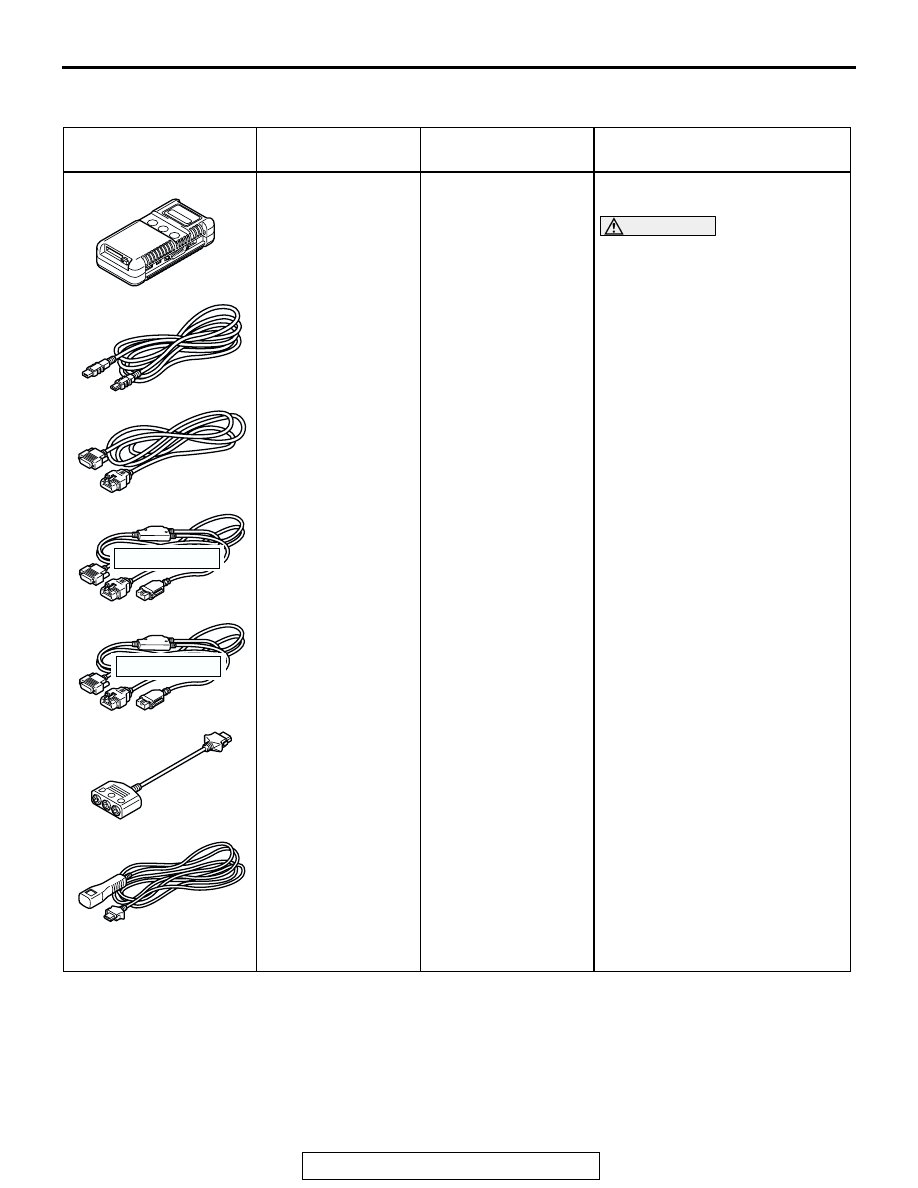
SPECIAL TOOL
M1549000300612
TOOL
TOOL NUMBER
AND NAME
SUPERSESSION
APPLICATION
MB991958
A: MB991824
B: MB991827
C: MB991910
D: MB991911
E: MB991914
F: MB991825
G: MB991826
MUT-III sub
assembly
A: Vehicle
communication
interface (V.C.I.)
B: MUT-III USB
cable
C: MUT-III main
harness a
(vehicles with
CAN
communication
system)
D: MUT-III Main
Harness B
(Vehicles without
CAN
communication
system)
E: MUT-III main
harness C (for
daimler chrysler
models only)
F: MUT-III
measurement
adapter
G: MUT-III trigger
harness
MB991824-KIT
NOTE: G: MB991826
MUT-III Trigger
Harness is not
necessary when
pushing V.C.I. ENTER
key.
SWS communication line check
(ECU check and service data)
CAUTION
For vehicles with CAN
communication, use MUT-III
main harness A to send
simulated vehicle speed. If you
connect MUT-III main harness B
instead, the CAN
communication does not
function correctly.
MB991910
MB991826
MB991958
MB991911
MB991914
MB991824
MB991827
MB991825
DO NOT USE
A
B
C
D
E
F
G
DO NOT USE