Mitsubishi Galant (2004+). Manual - part 1716


  Index      Mitsubishi     Mitsubishi Galant - service repair manual 2004 year


Search            


Content   ..  1714  1715  1716  1717   ..


Mitsubishi Galant (2004+). Manual - part 1716


AUTO-CRUISE CONTROL SYSTEM

ENGINE AND EMISSION CONTROL

17-5

CONSTRUCTION AND OPERATION

M2170002000027

SYSTEM OUTLINE

The PCM calculates the cruise control operation sta-
tus when the control section of the cruise control 
inside the PCM receives the input signals of the 
auto-cruise control switch, vehicle speed, and cancel 
system (stoplight switch and transmission range 

switch). To the engine control section it sends the tar-
get accelerator angle value for cruise control, to the 
A/T control section it issues a command to cancel 
OD, and to the gauge it issues an ON/OFF command 
for the auto-cruise control indicator light.
In the engine control section, the target throttle angle 
value is calculated from the target acceleration value 
for cruise control and the actual accelerator angle 
value, and the vehicle speed is controlled by apply-
ing the throttle actuator control motor.
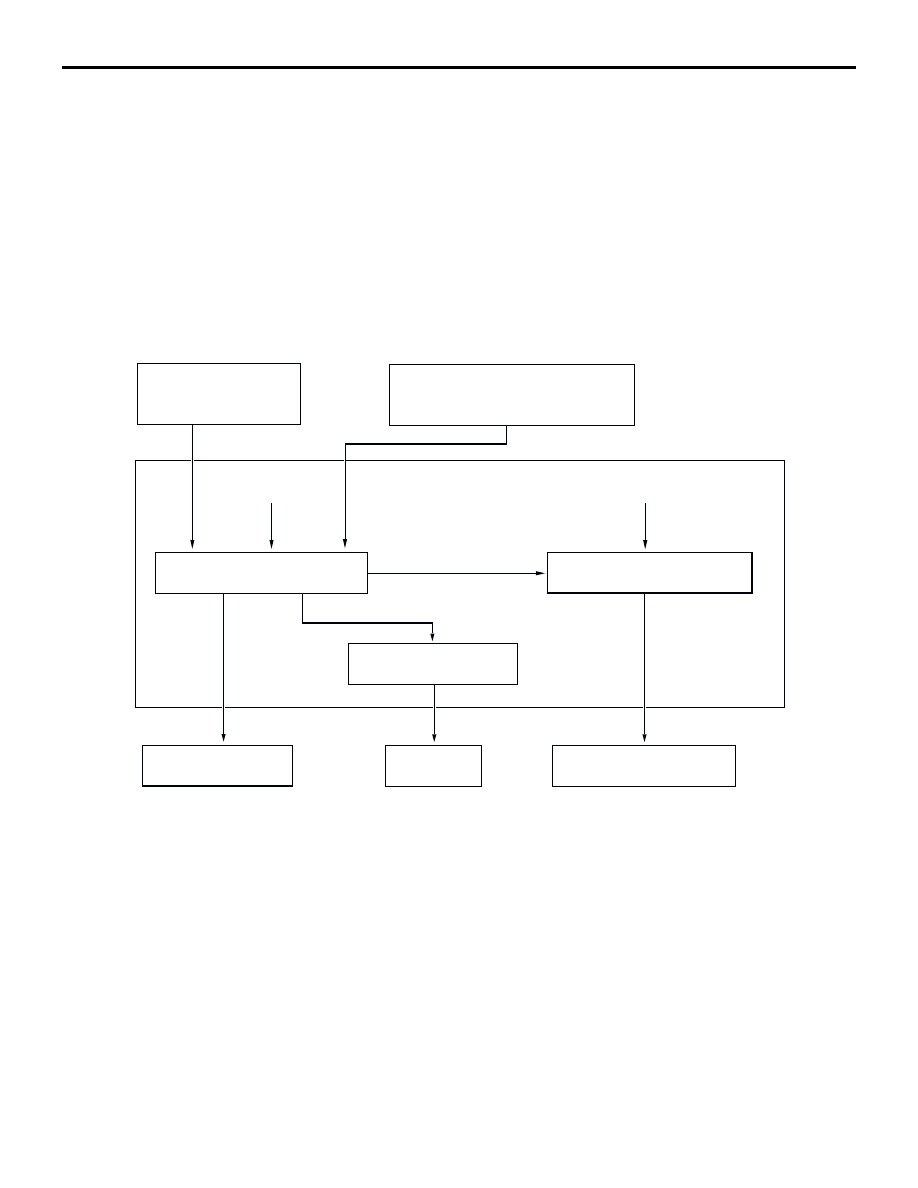
BLOCK DIAGRAM

SYSTEM FUNCTIONS
"COAST/SET" SWITCH FUNCTION

.

SET
The vehicle speed at the moment the "COAST/SET" 
switch was switched from OFF to ON while driving 
within the limit vehicle speed range is memorized as 
the "set vehicle speed" and thereafter the throttle 
actuator control motor is controlled so that 
fixed-speed driving at that speed is possible.
However, if the vehicle speed is set at 200 km/h (124 
mph) or higher, the speed of 200 km/h (124 mph) is 
saved as the vehicle speed, but if the vehicle speed 
is set above 205 km/h (127 mph), the vehicle will not 
reach the specified speed.

.

COAST
While the "COAST/SET" switch is held ON during 
auto-cruise driving, the vehicle keeps decelerating. If 
the "COAST/SET" switch is turned OFF before the 
vehicle speed decreases to 40 km/h (25 mph), the 
vehicle runs at the fixed speed at the moment the 
switch is turned OFF. If the "COAST/SET" switch is 
turned OFF after the vehicle speed decreases to less 
than 40 km/h (25 mph), the auto-cruise control is 
cancelled. 
However if the "COAST/SET" switch has been ON 
for 0.5 second or less, a tap-down operation is per-
formed [decelerating from the current speed by 1.6 
km/h (1 mph)]; at over 0.5 second, continuous decel-
eration is performed.

CANCEL SYSTEM
(STOPLIGHT SWITCH,
 TRANSMISSION RANGE SWITCH)

AUTO-CRUISE
CONTROL SWITCH

AUTOMATIC
TRANSAXLE

"CRUISE" INDICATOR
LIGHT

PCM

THROTTLE ACTUATOR
CONTROL MOTOR

TARGET ACCELERATOR
PEDAL OPENING
ANGLE

ENGINE CONTROL SECTION


CRUISE CONTROL SECTION

AC206197

VEHICLE
SPEED

ACTUAL ACCELERATOR
PEDAL OPENING ANGLE

A/T CONTROL SECTION


OVERDRIVE OFF CONTROL

TARGET THROTTLE
VALVE OPENING
ANGLE

AUTO-CRUISE CONTROL SYSTEM

ENGINE AND EMISSION CONTROL

17-6

"ACC/RES" SWITCH FUNCTION

.

RESUME
When fixed speed driving is cancelled by the condi-
tions given in "CANCEL FUNCTION," switching the 
"ACC/RES" switch from OFF to ON while driving at a 
speed higher than the set speed causes the vehicle 
to be driven at a fixed speed which is the speed 
memorized just before cancelling.

.

ACCELERATING
While the "ACC/RES" switch is ON during fixed 
speed driving, the vehicle accelerates to the target 
speed. The vehicle speed at the moment the switch 
is turned OFF is then memorized and the vehicle 
remains at this for fixed speed. When the 
"ACC/RES" switch is ON, the vehicle may accelerate 
to speeds above the high-speed limit but after the 
"ACC/RES" switch is turned OFF, the vehicle will 
remain at this high-speed limit.
However, if the "ACC/RES" switch has been ON for 
0.5 second or less, a tap-down operation is per-
formed [accelerating from the current speed by 1.6 
km/h (1 mph)]. At over 0.5 second, acceleration is 
performed continuously.

OVERDRIVE-CANCEL FUNCTION

When during fixed speed driving, the actual vehicle 
speed decreases to (or below) the memorized 
speed, the overdrive is cancelled temporarily, the 
memorized speed is restored when driving condi-
tions allow.
Overdrive is cancelled in the following case:

The vehicle speed is less than 130 km/h (81 
mph), and during fixed speed travel, the actual 
vehicle speed decreases from the preset speed 
by 7 km/h (4.3 mph).

CANCEL FUNCTION

When any of the following conditions occur, the 
auto-cruise control is cancelled.

"CRUISE" (MAIN) switch "OFF"

"CANCEL" switch ON

Stoplight switch ON (brake is applied)

Brake switch OFF (brake is applied)

Transmission range switch in "N" position

Vehicle speed at the low-speed limit [about 40 
km/h (25 mph)] or lower

Vehicle speed is lower than memorized speed by 
15 km/h (9 mph) or more

Vehicle speed once increasing to memorized 
speed less than 10 km/h (6 mph) and then 
decreasing more than 15 km/h (9 mph) with 
"ACC/RES" switch ON

Vehicle speed changing sharply

Stoplight switch input (malfunction or open circuit)

Defective auto-cruise control switch input voltage

When the cancel latch signal is ON (The cancel 
latch signal is ON when the signal of the engine 
control section and the signal of the cruise control 
section in PCM do not accord each other).

FAIL-SAFE FUNCTION

When any of the following conditions are met and do 
not activate auto-cruise control, and if the require-
ments are met during auto-cruise control, auto-cruise 
control is cancelled instantly. At this time, after the 
regular state is restored, auto-cruise control is possi-
ble again.

"COAST/SET" switch or "ACC/RES" switch held 
ON for 60 seconds or more

Fault in cancel state holding circuit

Vehicle speed is 40 km/h (25 mph) or more, or 
vehicle speed signal fails to be input for 0.1 sec-
ond or longer

During fixed-speed driving, if the vehicle exceeds 
the set speed by 10 km/h (6 mph), the 
fixed-speed control is cancelled momentarily, 
then resumed after the vehicle speed exceeds 
the set speed by 7 km/h (4 mph) or less.

When any of the following conditions are met, until 
the ignition is switched OFF once, do not activate 
auto-cruise control. If the requirements are met dur-
ing auto-cruise control, auto-cruise control is can-
celled instantly.

Defective PCM

Defective throttle position sensor

Defective accelerator pedal position sensor

AUTO-CRUISE CONTROL SYSTEM

ENGINE AND EMISSION CONTROL

17-7

SELF-DIAGNOSIS AND SERVICE DATA 
OUTPUT FUNCTIONS

.

Self-diagnosis
When there is a cancellation of the auto-cruise con-
trol system operation not intentionally made by the 
driver, it is possible to determine the cause simply by 
reading the diagnostic trouble code.

.

Diagnostic Trouble Code Chart

.

DIAGNOSTIC TROUBLE CODE INDICATION 
METHOD
The diagnostic trouble codes can be checked using 
the MUT-III scan tool. (Refer to Service Manual).

.

DIAGNOSTIC TROUBLE CODE CLEARING 
PROCEDURE
The diagnostic trouble codes can be cleared using 
the scan tool. (Refer to Service Manual).

.

Service Data Output
The service data output is shown in the following.

NOTE: If two or more actions are taken at the same 
time, codes are output in ascending order of code 
number.

CODE NO.

MAJOR CONTENTS OF DIAGNOSIS

15

Defective auto-cruise control switch

21

Defective cancel latch

22

Defective stoplight switch/brake switch

23

Defective PCM

MUT-III DISPLAY

ITEM NO.

SERVICE DATA ITEM

UNIT

APP SNS(MAIN)

12

Accelerator pedal position sensor

V

BRAKE SW

06

Brake switch

ON/OFF

CANCEL CODE

13

Cancel code

Displays a 
cancel code 
number.

CANCEL SWITCH

04

"CANCEL" switch

ON/OFF

CLUTCH SW

07

Transmission range switch

ON/OFF

CRUISE

09

Auto-cruise control operation

ON/OFF

IDLE SW SIG

08

Closed throttle position switch

ON/OFF

MAIN SW

01

"CRUISE" (MAIN) switch

ON/OFF

RESUME SWITCH

03

"ACC/RES" switch

ON/OFF

SET SWITCH

02

"COAST/SET" switch

ON/OFF

STOPLIGHT SW

05

Stoplight switch

ON/OFF

TP SNSR(MAIN)

11

Throttle position sensor

V

VSS

10

Vehicle speed signal

km/h

EMISSION CONTROL

ENGINE AND EMISSION CONTROL

17-8

EMISSION CONTROL

GENERAL DESCRIPTION

M2171000100322

The basic design is the same as that for the 2.4L 
engine installed in the LANCER WAGON except that 
the following modifications have been incorporated.

EMISSION CONTROL SYSTEM DIAGRAM

IMPROVEMENT/ADDITION

REMARK

With the adoption of the dual manifold catalytic 
converter (MCC), the heated oxygen sensors are 
located in the assembly of No. 1-No. 4 cylinders and 
No. 2-No. 3 cylinders.

Exhaust is reduced.

AK302229

MANIFOLD ABSOLUTE
PRESSURE SENSOR

THROTTLE ACTUATOR 
CONTROL MOTOR

CYLINDER 2, 3 
HEATED OXYGEN 
SENSOR (FRONT)

FUEL TANK
DIFFERENTIAL
PRESSURE SENSOR

FUEL TANK
TEMPERATURE
SENSOR

EVAPORATIVE EMISSION
VENTILATION VALVE

FUEL TANK

EVAPORATIVE 
EMISSION CANISTER

CYLINDER 1, 4
HEATED OXYGEN 
SENSOR (FRONT)

CYLINDER 1, 4
HEATED OXYGEN
SENSOR (REAR)

FUEL PRESSURE
REGULATOR

EVAPORATIVE 
EMISSION
VENTILATION 
SOLENOID

CYLINDER 2, 3
HEATED OXYGEN
SENSOR (REAR)

FUEL PUMP

FUEL
LEVEL
SENSOR

EVAPORATIVE
EMISSION
PURGE SOLENOID

EGR VALVE
(STEPPER MOTOR)

CATALYTIC CONVERTER

AB


Content   ..  1714  1715  1716  1717   ..