Mitsubishi Galant (2004+). Manual - part 167


  Index      Mitsubishi     Mitsubishi Galant - service repair manual 2004 year


Search            


Content   ..  165  166  167  168   ..


Mitsubishi Galant (2004+). Manual - part 167


CHARGING SYSTEM

TSB Revision

ENGINE ELECTRICAL

16-9

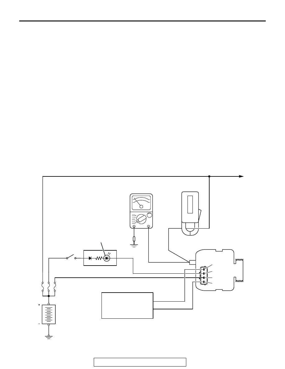
10.With the engine running at 2,500 r/min, turn the 

headlights and other lights on and off to adjust the 
generator load so that the value displayed on the 
ammeter is slightly above 30 A.
Read the voltmeter. Voltage reading at or below 
limit value means voltage drop between generator 
and battery is OK.

Limit value: maximum 0.3 V 

NOTE: When the generator output is high and the 
value displayed on the ammeter does not 
decrease to 30 A, set the value to 40 A. Read the 
value displayed on the voltmeter at this time.
In this case the limit value becomes maximum 0.4 
V.
Adjust the engine speed by gradually decreasing 
it until the value displayed on the ammeter is 30  
A. Take a reading of the value displayed on the 
voltmeter at this time.

11.If the value displayed on the voltmeter is above 

the limit value, there is probably a malfunction in 
the generator output wire. Check the wiring 
between the generator "B" terminal and the 
positive battery terminal (including fusible link).
If a terminal is not sufficiently tight or if the 
harness has become discolored due to 
overheating, repair and then test again.

12.After the test, run the engine at idle. 
13.Turn off all lights and turn the ignition switch to the 

"LOCK" (OFF) position.
NOTE: Vehicles for Canada, the headlight, tail-
light, etc. remain lit even when the lighting switch 
is in "OFF" position.

14.Disconnect the engine tachometer or scan tool 

MB991958.

15.Disconnect the negative battery cable.
16.Disconnect the ammeter and voltmeter.
17.Connect the negative battery cable.
18.Run the engine for 10 minutes at an idle.

OUTPUT CURRENT TEST

M1161001000391

AK303633

GENERATOR

AMMETER
(CLAMP-TYPE)

VOLTMETER

IGNITION
SWITCH

LOAD

B

FR

L

S

G

GENERATOR
MALFUNCTION
LIGHT

COMBINATION METER

BATTERY

+

AB

PCM

CHARGING SYSTEM

TSB Revision

ENGINE ELECTRICAL

16-10

Required Special Tool:
MB991958: Scan Tool (MUT-III Sub Assembly)

• MB991824: V.C.I.

• MB991827: MUT-III USB Cable

• MB991910: MUT-III Main Harness A

This test determines whether the generator outputs 
normal current. For best results, use a charging sys-
tem tester. If not available, follow the steps below.

WARNING

Battery posts, terminals and related acces-
sories contain lead and lead compounds. 
WASH HANDS AFTER HANDLING.

1. Before the test, always be sure to check the 

following.

• Generator installation

• Battery (Refer to GROUP 54A, Chassis Electrical 

− Battery − On-vehicle Service − Battery Check 

P.54A-5

.)

NOTE: The battery to be used should be slightly 
discharged. The load in a fully-charged battery 
will be insufficient and the test may not be able to 
be carried out correctly.

• Generator drive belt tension (Refer to GROUP 

00, General 

− Maintenance Service − 8. Drive 

Belts (For Generator, Power Steering Pump and 
Air Conditioning) (Check) 

P.00-43

.)

• Fusible link

• Abnormal noise from the generator while the 

engine is running.

2. Turn the ignition switch to the "LOCK" (OFF) 

position.

3. Disconnect the negative battery cable.

WARNING

Never use clips to connect the line. Loose 
connections (for example, using clips) will 
lead to a serious accident because of high 
current.

4. Connect a clamp-type DC test ammeter with a 

range of 0 

− 100 A to the generator "B" terminal 

output wire. 

5. Connect a voltmeter with a range of 0 

− 20 V 

between the generator "B" terminal and ground. 
(Connect the positive lead of the voltmeter to the 
"B" terminal, and then connect the negative lead 
of the voltmeter to ground.)

6. Connect the negative battery cable.
7. Connect an engine tachometer or scan tool 

MB991958.

8. Leave the hood open.
9. Check to be sure that the reading on the voltmeter 

is equal to the battery positive voltage.
NOTE: If the voltage is 0 V, the cause is probably 
an open circuit in the wire or fusible link between 
the generator "B" terminal and the battery positive 
terminal or malfunctioning voltmeter.

10.After turning on the headlights, start the engine.

NOTE: Because the current from the battery will 
soon drop after the engine is started, step 11 
should be carried out as quickly as possible in 
order to obtain the maximum current output value.

11.Immediately after setting the headlights to high 

beam and turning the heater blower switch to the 
highest position, increase the engine speed to 
2,500 r/min and read the maximum current output 
value displayed on the ammeter.

Limit value: 70 % of nominal current output

NOTE: For the nominal current output, refer to the 
Generator Specifications.
NOTE: The current output value will depend on 
the electrical load and the temperature of the gen-
erator body.
NOTE: If the electrical load is small while testing, 
the specified level of current may not be output 
even though the generator is normal. In such 
cases, increase the electrical load by leaving the 
headlights turned on for some time to discharge 
the battery or by using the lighting system in 
another vehicle, and then test again.
NOTE: The specified level of current also may not 
be output if the temperature of the generator body 
or the ambient temperature is too high. In such 
cases, cool the generator and then test again.

12.The reading on the ammeter should be above the 

limit value. If the reading is below the limit value 
and the generator output wire is normal, remove 
the generator from the engine and check the 
generator.

13.Run the engine at idle speed after the test.
14.Turn the ignition switch to the "LOCK" (OFF) 

position.

15.Disconnect the engine tachometer or scan tool 

MB991958.

16.Disconnect the negative battery cable.
17.Disconnect the ammeter and voltmeter .
18.Connect the negative battery cable.
19.Run the engine for 10 minutes at an idle.

CHARGING SYSTEM

TSB Revision

ENGINE ELECTRICAL

16-11

REGULATED VOLTAGE TEST

M1161001100387

Required Special Tools:

• MB991958: Scan Tool (MUT-III Sub Assembly)

• MB991824: V.C.I.

• MB991827: MUT-III USB Cable

• MB991910: MUT-III Main Harness A

• MB991519: Generator Harness Connector

This test determines whether the voltage regulator is 
correctly controlling the generator output voltage.

WARNING

Battery posts, terminals and related acces-
sories contain lead and lead compounds. 
WASH HANDS AFTER HANDLING.

1. Always be sure to check the following before the 

test:

• Generator installation

• Check to be sure that the battery installed in the 

vehicle is fully charged. (Refer to GROUP 54A, 
Chassis Electrical 

− Battery − On-vehicle Service 

− Battery Check 

P.54A-5

.)

• Generator drive belt tension (Refer to GROUP 

00, General 

− Maintenance Service − 8. Drive 

Belts (For Generator, Power Steering Pump and 
Air Conditioning) (Check) 

P.00-43

.)

• Fusible link

• Abnormal noise from the generator while the 

engine is running.

2. Turn the ignition switch to the "LOCK" (OFF) 

position.

3. Disconnect the negative battery cable.
4. Use the special tool (Generator harness 

connector: MB991519) to connect a digital-type 
voltmeter between the generator "S" terminal and 
ground. (Connect the positive lead of the 
voltmeter to the "S" terminal, and then connect the 
negative lead of the voltmeter to a secure ground 
or to the negative battery terminal.)

5. Connect a clamp-type DC test ammeter with a 

range of 0 

− 100 A to the generator "B" terminal 

output wire.

6. Reconnect the negative battery cable.
7. Connect an engine tachometer, or scan tool 

MB991958.

8. Turn the ignition switch to the "ON" position and 

check that the reading on the voltmeter is equal to 
the battery positive voltage.
NOTE: If the voltage is 0 V, the cause is probably 
an open circuit in the wire or fusible link between 
the generator "S" terminal and the battery positive 
terminal or malfunctioning voltmeter.

9. Check to be sure that all lights and accessories 

are off.

10.Start the engine.
11.Increase the engine speed to 2,500 r/min.
12.Read the value displayed on the voltmeter when 

the current output by the generator becomes 10 A 
or less.

AK303634

PCM

AB

BATTERY

IGNITION
SWITCH

AMMETER 
(CLAMP-TYPE)

LOAD

BLACK

MB991519

VOLTMETER (DIGITAL-TYPE)

RED

YELLOW

BLUE

GENERATOR

B

FR

L

S

G

GENERATOR
MALFUNCTION
LIGHT

COMBINATION 
METER

CHARGING SYSTEM

TSB Revision

ENGINE ELECTRICAL

16-12

13.If the voltage reading conforms to the value in the 

voltage regulation table, then the voltage regulator 
is operating normally.
If the voltage is outside the standard value, there 
is a malfunction of the voltage regulator or the 
generator (Refer to the following table).

14.After the test, lower the engine speed to idle.

15.Turn the ignition switch to the "LOCK" (OFF) 

position.

16.Disconnect the engine tachometer or scan tool 

MB991958.

17.Disconnect the negative battery cable.
18.Disconnect the ammeter and voltmeter.
19.Connect the negative battery cable.
20.Run the engine for 10 minutes at an idle.

VOLTAGE REGULATION TABLE

WAVE PATTERN CHECK USING AN 
OSCILLOSCOPE

M1161001200180

.

MEASUREMENT METHOD
Connect the oscilloscope special patterns pick-up to the gener-
ator "B" terminal.

.

STANDARD WAVEFORM

INSPECTION TERMINAL

VOLTAGE REGULATOR 
AMBIENT TEMPERATURE [

°

(

°F)]

STANDARD VALUE (V)

Terminal "S"

−20 (−4)

14.2 

− 15.4

20 (68)

13.9 

− 14.9

60 (140)

13.4 

− 14.5

80 (176)

13.1 

− 14.2

AKX00188

GENERATOR

OSCILLOSCOPE

"B" TERMINAL

PROBE

AB

Observation Conditions

FUNCTION

SPECIAL PATTERNS

Pattern height

Variable

Variable knob

Adjust while viewing the wave 
pattern

Pattern selector

Raster

Engine revolutions

Curb idle speed


Content   ..  165  166  167  168   ..