Mitsubishi Galant (2004+). Manual - part 1577


  Index      Mitsubishi     Mitsubishi Galant - service repair manual 2004 year


Search            


Content   ..  1575  1576  1577  1578   ..


Mitsubishi Galant (2004+). Manual - part 1577


SRS AIR BAG DIAGNOSIS

TSB Revision

SUPPLEMENTAL RESTRAINT SYSTEM (SRS)

52B-201

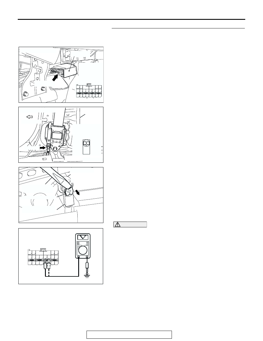
STEP 4. Check the passenger's seat belt pre-tensioner 
circuit. Measure the voltage at the SRS-ECU connector 
C-120.

(1) Disconnect SRS-ECU connector C-120.

(2) Disconnect passenger's seat belt pre-tensioner connector 

D-33. Use a flat-tipped screwdriver to unlock the locking 
button at the harness side connector by withdrawing it 
toward you in two stages, and then disconnect the 
connector.

(3) Turn the ignition switch to the "ON" position,

CAUTION

Do not insert a test probe into the terminal from its front 
side directly, as the connector contact pressure may be 
weakened.
(4) Measure the voltage between C-120 harness side 

connector terminals 59, 60 and body ground.
Voltage should measure 0 volt.

Q: Is the circuit normal?

YES : Erase the diagnostic trouble code memory, and check 

the diagnostic trouble code. If DTC B1462 sets, 
replace the SRS-ECU (Refer to 

P.52B-365

). Then go 

to Step 6.

NO :  Go to Step 5.

AC305362

CONNECTOR: C-120

C-120 (Y)

AG

SRS-ECU

63

55

51

69

61

66

58

65

64

56 57

68

60

67

59

70

62

53

52 B

A

54

C-120 
Harness side
connector 
(rear view)

AC307915 AC

CONNECTOR: D-33

D-33 (B)

FORWARD

CENTER 
PILLAR

HARNESS SIDE
CONNECTOR
(FRONT VIEW)

2 1

AC103556AU

LOCKING BUTTON

FLAT-TIP SCREW
DRIVER

D-33 HARNESS 
SIDE CONNECTOR

D-33 PASSENGER'S 
SEAT BELT
PRE-TENSIONER
CONNECTOR

AC301577

63

55

51

69

61

66

58

65

64

56 57

68

60

67

59

70

62

53

52 B

A

54

AD

C-120 HARNESS SIDE
CONNECTOR
(REAR VIEW)

SRS AIR BAG DIAGNOSIS

TSB Revision

SUPPLEMENTAL RESTRAINT SYSTEM (SRS)

52B-202

STEP 5. Check the harness wires for short circuit to power 
supply between SRS-ECU connector C-120 (terminal No.59 
and 60) and passenger's seat belt pre-tensioner connector 
D-33 (terminal No.1 and 2).

Q: Are the harness wires between SRS-ECU connector 

C-120 (terminal No.59 and 60) and passenger's seat belt 
pre-tensioner connector D-33 (terminal No.1 and 2) in 
good condition?
YES : 
Go to Step 6.
NO :  Replace the harness wires between SRS-ECU 

connector C-120 and passenger's seat belt 
pre-tensioner connector D-33. Then go to Step 6.

STEP 6. Recheck for diagnostic trouble code. 

Check again if the DTC is set.
(1) Erase the DTC.
(2) Turn the ignition switch to the "ON" position.

(3) Check if the DTC is set.
(4) Turn the ignition switch to the "LOCK" (OFF) position.
Q: Is DTC B1462 set?

YES : Return to Step 1.
NO :  The procedure is complete.

AC305362

CONNECTOR: C-120

C-120 (Y)

AG

SRS-ECU

63

55

51

69

61

66

58

65

64

56 57

68

60

67

59

70

62

53

52 B

A

54

C-120 
Harness side
connector 
(rear view)

AC307915 AC

CONNECTOR: D-33

D-33 (B)

FORWARD

CENTER 
PILLAR

HARNESS SIDE
CONNECTOR
(FRONT VIEW)

2 1

AC305412

AB

MB991910

DATA LINK

CONNECTOR

MB991824

MB991827

SRS AIR BAG DIAGNOSIS

TSB Revision

SUPPLEMENTAL RESTRAINT SYSTEM (SRS)

52B-203

DTC B1463: Seat Belt Pre-Tensioner (RH) (Squib) System Fault for Ground Circuit (Short-Circuit to 
Ground)

CAUTION

If DTC B1463 is set in the SRS-ECU, always diag-
nose the CAN main bus line.

.

CIRCUIT OPERATION
The SRS-ECU judges how severe a collision is by 
detecting signals from the front impact sensors and 
the front air bag analog G-sensor. If the impact is 
over a predetermined level, the SRS-ECU sends an 
ignition signal. At this time, if the front air bag safing 
G-sensor is on, the pre-tensioner will deploy. 

.

DTC SET CONDITIONS
This DTC is set if there is abnormal resistance 
between the input terminals of the passenger's seat 
belt pre-tensioner (squib).

.

TROUBLESHOOTING HITS

• Damaged wiring harnesses or connectors

• Short to the ground in the passenger's seat belt 

pre-tensioner (squib) harness

• Malfunction of the SRS-ECU

.

SEAT BELT
PRETENSIONER
(RH)

MICROCOMPUTER

AIR BAG DRIVE CIRCUIT

CONNECTOR
LOCK SWITCH

CONNECTOR
LOCK SWITCH

SRS-ECU

AC210784 AB

NOTE

: CONNECTOR

CONNECTED

:  ON
CONNECTOR

DISCONNECTED

:  OFF

Passenger's (Front) Seat Belt Pre-tensioner (Squib)

AC305362

CONNECTOR: C-120

C-120 (Y)

AC

SRS-ECU

AC307915 AB

CONNECTOR: D-33

D-33 (B)

FORWARD

CENTER 
PILLAR

SRS AIR BAG DIAGNOSIS

TSB Revision

SUPPLEMENTAL RESTRAINT SYSTEM (SRS)

52B-204

DIAGNOSIS

Required Special Tools:

• MB991958: Scan Tool (MUT-III Sub Assembly)

• MB991824: Vehicle Communication Interface (V.C.I.)

• MB991827: MUT-III USB Cable

• MB991910: MUT-III Main Harness A

• MB991865: Dummy resistor

• MB991884: Resister harness (For Pre-tensioner)

STEP 1. Using scan tool MB991958, diagnose the CAN bus 
line.

CAUTION

To prevent damage to scan tool MB991958, always turn the 
ignition switch to the "LOCK" (OFF) position before con-
necting or disconnecting scan tool MB991958.
(1) Connect scan tool MB991958. Refer to "How to connect the 

scan tool 

P.52B-30

."

(2) Turn the ignition switch to the "ON" position.
(3) Diagnose the CAN bus line.
(4) Turn the ignition switch to the "LOCK" (OFF) position.
Q: Is the CAN bus line found to be normal?

YES : Go to Step 2.
NO :  Repair the CAN bus line (Refer to GROUP 54C, 

Diagnosis 

P.54C-14

).

AC305412

AB

MB991910

DATA LINK

CONNECTOR

MB991824

MB991827


Content   ..  1575  1576  1577  1578   ..