Mitsubishi Galant (2004+). Manual - part 1553


  Index      Mitsubishi     Mitsubishi Galant - service repair manual 2004 year


Search            


Content   ..  1551  1552  1553  1554   ..


Mitsubishi Galant (2004+). Manual - part 1553


SRS AIR BAG DIAGNOSIS

TSB Revision

SUPPLEMENTAL RESTRAINT SYSTEM (SRS)

52B-105

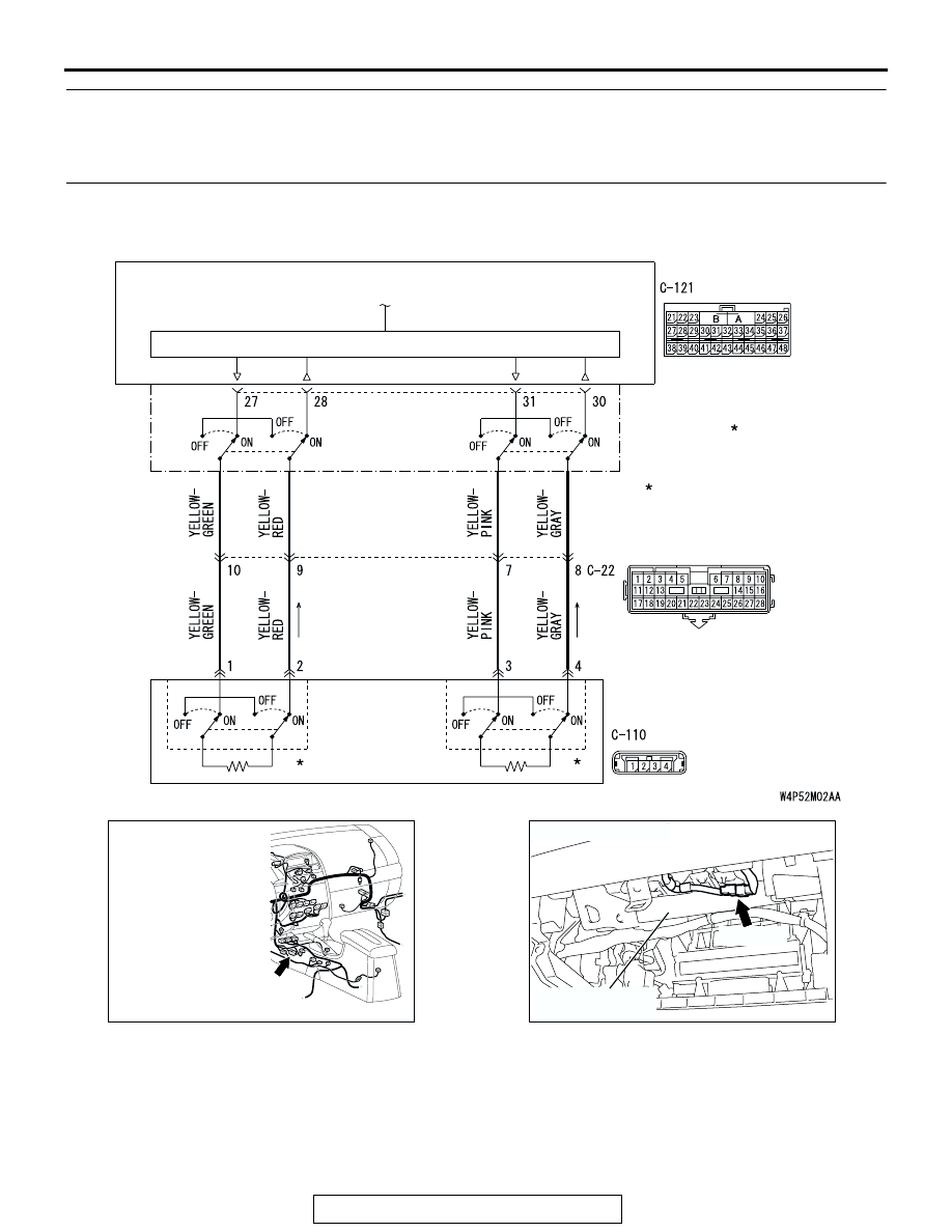
DTC B1413: Passenger’s (Front) Air Bag Module (1st Squib) System Fault for Ground Circuit 
(Short-Circuited to Ground)
DTC B1493: Passenger’s (Front) Air Bag Module (2nd Squib) System Fault for Ground Circuit 
(Short-Circuited to Ground)

AIR BAG MODULE 
(SQUIB) 
(PASSENGER'S SIDE)

AIR BAG DRIVE CIRCUIT

SRS-ECU

CONNECTOR
LOCK SWITCH

Passenger's (Front) Air Bag Module (1st Squib and 2nd Squib) Circuit

NOTE
  : CONNECTOR CONNECTED
    : ON
    CONNECTOR DISCONNECTED
    : OFF

AC305233 AO

CONNECTOR: C-22

C-22 (Y)

AC307137AD

C-110 (Y)

FRONT DECK
CROSSMEMBER

CONNECTOR: C-110

SRS AIR BAG DIAGNOSIS

TSB Revision

SUPPLEMENTAL RESTRAINT SYSTEM (SRS)

52B-106

CAUTION

If DTC B1413 <1st squib> or B1493 <2nd squib> 
is set in the SRS-ECU, always diagnose the CAN 
main bus line.

.

CIRCUIT OPERATION

• The SRS-ECU judges how severe a collision is 

by detecting signals from the front impact sensors 
and the front air bag analog G-sensor. If the 
impact is over a predetermined level, the 
SRS-ECU sends an ignition signal. At this time, if 
the front air bag safing G-sensor is on, the SRS 
air bag will inflate. 

• The ignition signal is input to the air bag module 

via the clock spring to inflate the air bag.

.

DTC SET CONDITIONS
This DTC is set if there is abnormal resistance 
between the input terminals of the passenger's air 
bag module (squib). However, if no DTC resets, the 
SRS warning light will be switched off (DTC will be 
retained). 

.

TROUBLESHOOTING HINTS

• Damaged harness wires and connectors

• Short to the ground in the passenger's air bag 

module (squib) harness

• Malfunction of the SRS-ECU

.

DIAGNOSIS

Required Special Tools:

• MB991958: Scan Tool (MUT-III Sub Assembly)

• MB991824: Vehicle Communication Interface (V.C.I.)

• MB991827: MUT-III USB Cable

• MB991910: MUT-III Main Harness A (Vehicles with CAN 

Communication System)

• MB991865: Dummy resistor

• MB991866: Resister harness

AC305362

CONNECTOR: C-121

C-121 (Y)

AD

SRS-ECU

SRS AIR BAG DIAGNOSIS

TSB Revision

SUPPLEMENTAL RESTRAINT SYSTEM (SRS)

52B-107

STEP 1. Using scan tool MB991958, diagnose the CAN bus 
line.

CAUTION

To prevent damage to scan tool MB991958, always turn the 
ignition switch to the "LOCK" (OFF) position before con-
necting or disconnecting scan tool MB991958.
(1) Connect scan tool MB991958. Refer to "How to connect the 

scan tool 

P.52B-30

."

(2) Turn the ignition switch to the "ON" position.
(3) Diagnose the CAN bus line.
(4) Turn the ignition switch to the "LOCK" (OFF) position.
Q: Is the CAN bus line found to be normal?

YES : Go to Step 2.
NO :  Repair the CAN bus line (Refer to GROUP 54C, 

Diagnosis 

P.54C-14

).

STEP 2. Recheck for diagnostic trouble code.

Check again if the DTC is set.
(1) Erase the DTC.
(2) Turn the ignition switch to the "ON" position.

(3) Check if the DTC is set.
(4) Turn the ignition switch to the "LOCK" (OFF) position.
Q: Is the DTC set?

YES : Go to Step 3.
NO :  There is an intermittent malfunction such as poor 

engaged connector(s) or open circuit (Refer to 
GROUP 00, How to Cope with Intermittent 
Malfunction 

P.00-6

).

AC305412

AB

MB991910

DATA LINK

CONNECTOR

MB991824

MB991827

AC305412

AB

MB991910

DATA LINK

CONNECTOR

MB991824

MB991827

SRS AIR BAG DIAGNOSIS

TSB Revision

SUPPLEMENTAL RESTRAINT SYSTEM (SRS)

52B-108

STEP 3. Check the passenger's air bag module. (Using 
scan tool MB991958, read the diagnostic trouble code.)

(1) Disconnect the negative battery terminal.
(2) Disconnect the passenger’s air bag module connector 

C-110.

(3) Slide the outer housing of the clock spring side of 

passenger’s air bag module connector C-110 in the arrow 
direction shown, and disconnect the connector.

(4) Connect special tool MB991865 to special tool MB991866.

CAUTION

Do not insert a test probe into the terminal from its front 
side directly, as the connector contact pressure may be 
weakened.
(5) Insert special tool MB991866 into the harness side 

connector C-110 (terminal No.1 and 2 <1st squib> or 
terminal No.3 and 4 <2nd squib>) by backprobing.

(6) Connect the negative battery terminal.
(7) Erase the diagnostic trouble code memory, and check the 

diagnostic trouble code.

Q:  Is DTC B1413 <1st squib> B1493 <2nd squib> set?

YES : Go to Step 4.
NO :  Replace the passenger's air bag module. (Refer to 

P.52B-368

). Then go to Step 6.

AC307137AC

C-110 (Y)

FRONT DECK
CROSSMEMBER

CONNECTOR: C-110

HARNESS SIDE 
CONNECTOR
(REAR VIEW)

AC306561AD

OUTER HOUSING OF THE PASSENGER'S 
AIR BAG MODULE CONNECTOR C-110

AC306760AB

MB991865 (DUMMY 
RESISTOR: 3 

Ω)

MB991866
(RESISTOR HARNESS)

C-110 HARNESS 
CONNECTOR

C-110
PASSENGER'S
AIR BAG MODULE 
CONNECTOR


Content   ..  1551  1552  1553  1554   ..