Mitsubishi Galant (2004+). Manual - part 1521


  Index      Mitsubishi     Mitsubishi Galant - service repair manual 2004 year


Search            


Content   ..  1519  1520  1521  1522   ..


Mitsubishi Galant (2004+). Manual - part 1521


TRACTION CONTROL SYSTEM (TCL) DIAGNOSIS

TSB Revision

TRACTION CONTROL SYSTEM (TCL)

13D-25

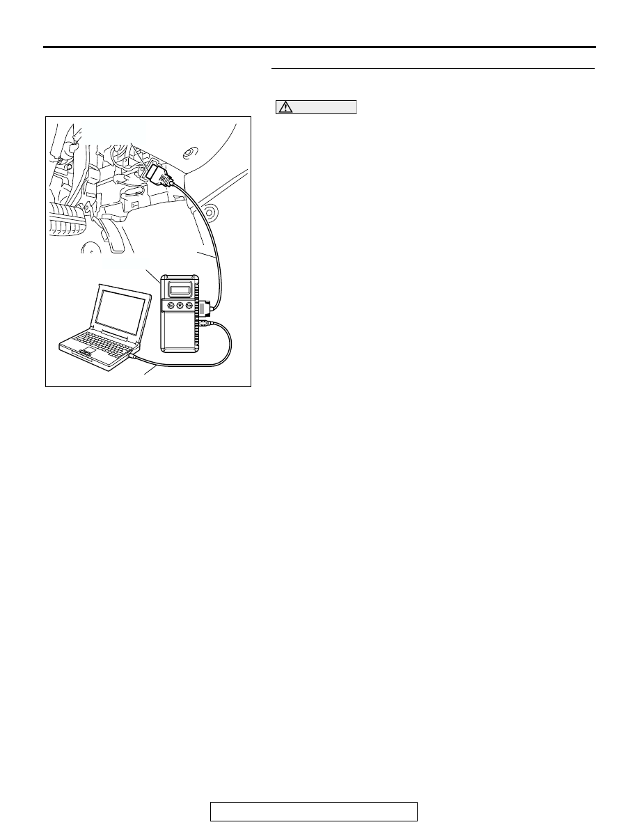
STEP 6. Recheck for diagnostic trouble code.

Check again if the DTC is set.

CAUTION

To prevent damage to scan tool MB991958, always turn the 
ignition switch to the "LOCK" (OFF) position before con-
necting or disconnecting scan tool MB991958.
(1) Connect scan tool MB991958 to the data link connector 

(Refer to 

P.13D-4

).

(2) Turn the ignition switch to the "ON" position.
(3) Erase the DTC (Refer to 

P.13D-4

).

(4) Turn the ignition switch to the "LOCK" (OFF) position.
(5) Turn the ignition switch to the "ON" position.
(6) Check if the DTC is set.
(7) Turn the ignition switch to the "LOCK" (OFF) position.
(8) Disconnect scan tool MB991958.
Q: Is DTC U1120 set?

YES : Return to Step 1 .
NO :  The procedure is complete.

AC305412

AB

MB991910

DATA LINK

CONNECTOR

MB991824

MB991827

TRACTION CONTROL SYSTEM (TCL) DIAGNOSIS

TSB Revision

TRACTION CONTROL SYSTEM (TCL)

13D-26

U1400 Dynamic range error APS1

.

DTC SET CONDITION
This code is set when the MFI system sets either of 
DTC code Nos. P2138, P2122 or P2123.

.

TROUBLESHOOTING HINTS (The most likely 
causes for these DTCs are to set are:)

• Malfunction of the MFI system

DIAGNOSIS

Check whether the MFI system sets either of diagnostic trouble 
code Nos. P2138, P2122 or P2123, and repair if necessary. 
(Refer to GROUP 13B, MFI Diagnosis - How to Read and 
Erase Diagnostic Trouble Code 

P.13B-5

).

SYMPTOM CHART

M1136003400029

SYMPTOM

INSPECTION 
PROCEDURE NO.

REFERENCE 
PAGE

Communication with 
scan tool is not 
possible

Communication with all systems is 
impossible

-

Group 13B, 
Symptom 
Procedures 

− 

Inspection 
Procedure 1 

P.13B-965

.

Communication with the ABS/TCL-ECU 
only is impossible

-

Group 35B, 
Symptom 
Procedures 

− 

Inspection 
Procedure 1 

P.35B-87

.

When the ignition switch is turned to the "ON" position (engine 
stopped), the "TCL OFF" indicator light dose not illuminate.

1

P.13D-27

When the ignition switch is turned to the "ON" position (engine 
stopped), the TCL work indicator light dose not illuminate.

2

The "TCL OFF" indicator light remains illuminated after the engine 
is started.

3

The TCL work indicator light remains illuminated after the engine 
is started.

4

When the TCL switch is push on, TCL system does not be 
cancelled.

5

P.13D-32

TCL system dose not operate.

6

P.13D-39

TRACTION CONTROL SYSTEM (TCL) DIAGNOSIS

TSB Revision

TRACTION CONTROL SYSTEM (TCL)

13D-27

SYMPTOM PROCEDURES

INSPECTION PROCEDURE 1: When the Ignition Switch is Turned to the "ON" Position (Engine 
Stopped), the "TCL OFF" Indicator Light dose not Illuminate. INSPECTION PROCEDURE 2: When the 
Ignition Switch is Turned to the "ON" Position (Engine Stopped), the TCL Work Indicator Light dose 
not Illuminate. INSPECTION PROCEDURE 3: The "TCL OFF" Indicator Light Remains Illuminated 
After the Engine is Started. INSPECTION PROCEDURE 4: The TCL Work Indicator Light Remains 
Illuminated After the Engine is Started.

BATTERY

IGNITION SWITCH (IG1)

JOINT
CONNECTOR (1)

JOINT         
CONNECTOR (3)

RELAY
BOX

JUNCTION
BLOCK

COMBINATION
METER

JOINT
CONNECTOR (4)

ABS/TCL-ECU

AC307013

"TCL OFF" Indicator Light and TCL Work Indicator Light Drive Circuit

AB

TRACTION CONTROL SYSTEM (TCL) DIAGNOSIS

TSB Revision

TRACTION CONTROL SYSTEM (TCL)

13D-28

.

CIRCUIT OPERATION

• ABS/TCL-ECU send the illumination signal of 

"TCL OFF" indicator light and TCL work indicator 
light to the combination meter via the CAN com-
munication.

• ABS/TCL-ECU operates the "TCL OFF" indicator 

light and the TCL work indicator light for three 
seconds after the ignition switch is turned "ON" 
position for bulb check.

.

AC305209AB

A-02 (GR)

CONNECTOR: A-02 

A-02 HARNESS CONNECTOR:

COMPONENT SIDE

AC305232AO

CONNECTORS: C-01, C-02, C-03, C-29, C-101

C-29

C-01

C-101

C-03

C-02

C-01 AND C-03

HARNESS CONNECTOR:

COMPONENT SIDE

C-02 HARNESS

CONNECTOR:

COMPONENT SIDE

C-29 MALE SIDE

CONNECTOR

C-101 HARNESS

CONNECTOR:

COMPONENT SIDE

AC305720

C-215 HARNESS CONNECTOR:

COMPONENT SIDE

JUNCTION BLOCK

(FRONT VIEW)

AB

C-215

C-211

CONNECTORS: C-211, C-215

C-211 HARNESS CONNECTOR:

COMPONENT SIDE


Content   ..  1519  1520  1521  1522   ..