Mitsubishi Galant (2004+). Manual - part 1435


  Index      Mitsubishi     Mitsubishi Galant - service repair manual 2004 year


Search            


Content   ..  1433  1434  1435  1436   ..


Mitsubishi Galant (2004+). Manual - part 1435


POWER STEERING GEAR BOX AND LINKAGE

TSB Revision

POWER STEERING

37A-49

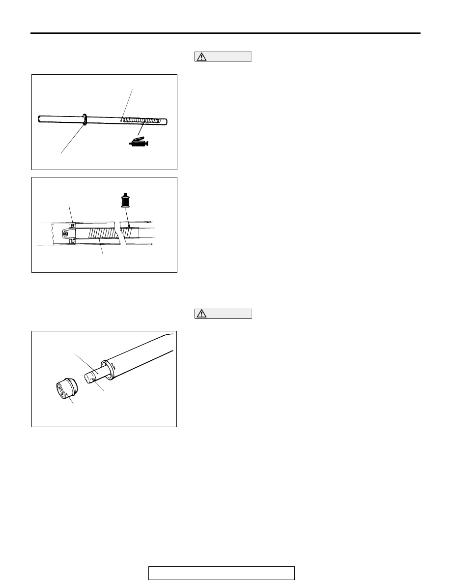
>>E<< STEERING GEAR RACK INSTALLATION

CAUTION

Do not close the vent hole in the rack with grease.
1. Apply a coating of multipurpose grease to the rack teeth 

face.

2. Cover the rack serrations with special tool MB991213.
3. Apply GENUINE MITSUBISHI POWER STEERING FLUID 

to special tool MB991213.

4. Align the center of the oil seal with the rack to prevent the 

retainer spring from slipping. Slowly insert the rack from 
power the cylinder side.

.

>>F<< STEERING GEAR BUSHING (RACK BUSHING) 
INSTALLATION

CAUTION

Do not allow oil seal retainer spring to slip out.
Wrap the rack end with vinyl tape, apply a coating of GENUINE 
MITSUBISHI POWER STEERING FLUID, and then install the 
rack bushing and rack stopper.

.

ACX01154 AB

SEAL RING, O-RING

VENT HOLE

ACX01155

MB991213

AB

OIL SEAL

ACX01157

RACK BUSHING

AD

VINYL TAPE

RACK

POWER STEERING GEAR BOX AND LINKAGE

TSB Revision

POWER STEERING

37A-50

>>G<< STEERING GEAR PISTON CLIP (CIRCLIP) 
INSTALLATION

CAUTION

Insert the circlip to the rack stopper hole while turning the 
rack stopper clockwise.
Insert the circlip to the rack stopper hole through the cylinder 
hole. Turn the rack stopper clockwise and insert the circlip 
firmly.

.

>>H<< OIL SEAL/SPECIAL BEARING INSTALLATION
Apply a coating of GENUINE MITSUBISHI POWER STEER-
ING FLUID to the outside of the oil seal/special bearing. Using 
special tools MB990938 and MB991203, press the oil seal/spe-
cial bearing into the valve housing.

.

>>I<< SEAL RING INSTALLATION
Because the seal rings expand after installation, tighten after 
installing by using special tool MB991317 to compress the seal 
rings, or press down by hand.

.

>>J<< OIL SEAL INSTALLATION

CAUTION

To eliminate a seal malfunction at the valve housing align-
ment surface, the upper surface of the oil seal should 
project outward approximately 1 mm (0.04 inch) from the 
housing edge surface.
Using special tool MB991152, press the oil seal into the valve 
housing.

.

ACX01158

CIRCLIP

SLOT

SLOT

AB

CIRCLIP

ACX01159AC

MB990938

MB991203

OIL SEAL

MB991203

BEARING

MB990938

ACX01160 AB

MB991317

ACX01161

HOUSING

AB

OIL
SEAL

APPROXIMATELY
1 mm(0.04 in)

MB991152

POWER STEERING GEAR BOX AND LINKAGE

TSB Revision

POWER STEERING

37A-51

>>K<< STEERING GEAR PLUG (END PLUG) 
INSTALLATION
1. Apply 3M

TM

 AAD Part number 8661, 8663, 8672, 8678, 

8679 or equivalent to the threaded part of the end plug.

2. Secure the threaded portion of the end plug at two places by 

using a punch.

.

>>L<< STEERING GEAR RACK SUPPORT 
COVER/STEERING GEAR INNER NUT (JAM NUT) 
INSTALLATION
1. Position the rack at its center.
2. Apply 3M

TM

 AAD Part number 8661, 8663, 8672, 8678, 

8679 or equivalent to the threaded part of the rack support 
cover.

3. Use special tool MB991204 to tighten the rack support cover 

to 12 

± 2 N⋅m (107 ± 17 in-lb).

4. Turn the rack support cover 10 degree angle 

counterclockwise.

5. Use special tool MB991204 to hold the rack support cover, 

and then tighten the jam nut to 59 

± 10 N⋅m (44 ± 7 ft-lb).

.

>>M<< TOTAL PINION TORQUE ADJUSTMENT

CAUTION

• Be sure there is no ratcheting or catching when operat-

ing the rack towards the shaft.

• Measure the total pinion torque through the whole 

stroke of the rack.

1. Using special tool MB991006, rotate the pinion shaft at the 

rate of one rotation in 4 to 6 seconds to check the total 
pinion torque and the change in torque.

Standard value:
Total pinion torque: 0.8 

 1.9 Nm (7.1  16.8 in-lb)

[Change in torque: 0.7 N

m (6.2 in-lb) or less]

CAUTION

When adjusting, set at the highest value of the standard 
value range.

NOTE: If the total pinion toque cannot be adjusted to the 
standard value within the standard range, replace the power 
steering gear and linkage assembly.

ACX01162 AB

END PLUG

END PLUG

AC001009 AB

MB991204

AC306793

MB991006

AB

RACK SUPPORT 
COVER

POWER STEERING GEAR BOX AND LINKAGE

TSB Revision

POWER STEERING

37A-52

2. If the total pinion torque or the change in torque is outside 

the standard value, loosen the rack support cover once and 
retighten it to the specified torque 12 

± 2 N⋅m (107 ± 17 

in-lb). And then loosen the rack support cover 10 degrees, 
and check the pinion torque again.

.

>>N<< STEERING GEAR WASHER (TAB 
WASHER)/STEERING TIE ROD INSTALLATION
After installing the tie rod to the rack, fold tab washer end (two 
locations) to tie rod notch.

.

>>O<< STEERING GEAR BAND (BELLOWS BAND) 
INSTALLATION
1. Turn the adjusting bolt of special tool MB991561 to adjust 

the opening dimension (W) to the standard value.
NOTE: The dimension (W) is adjusted by approximately 0.7 
mm (0.03 inch) per one turn.
NOTE: Do not turn the adjusting bolt more than one turn.

Standard value (W): 1.9 mm (0.07 inch)
<When more than 1.9 mm (0.07 inch)>: Screw in the 
adjusting bolt.
<When less than 1.9 mm (0.07 inch)>: Loosen the 
adjusting bolt.

CAUTION

• Hold the rack housing, and use special tool MB991561 

to crimp the bellows band securely.

• Crimp the bellows band until special tool MB991561 

touches the stopper.

2. Use special tool MB991561 to crimp the bellows band.

ACX01163 AB

ACX01164 AB

W

MB991561

ADJUSTING BOLT

STOPPER

ACX01165 AB

MB991561


Content   ..  1433  1434  1435  1436   ..