Mitsubishi Galant (2004+). Manual - part 1404


  Index      Mitsubishi     Mitsubishi Galant - service repair manual 2004 year


Search            


Content   ..  1402  1403  1404  1405   ..


Mitsubishi Galant (2004+). Manual - part 1404


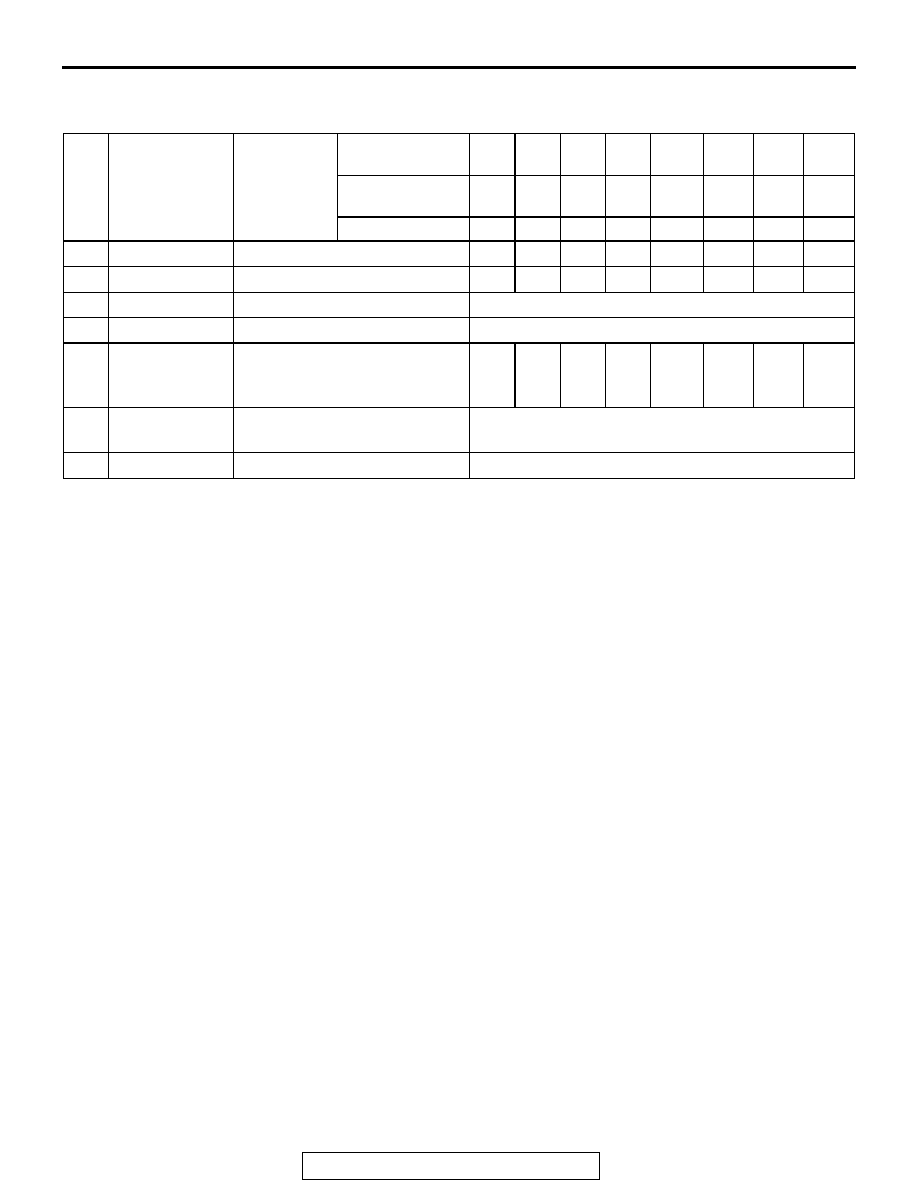
SCHEDULED MAINTENANCE TABLE

TSB Revision

GENERAL

00-39

SCHEDULED MAINTENANCE UNDER SEVERE USAGE CONDITIONS
Maintenance should be carried out according to the following table:

Severe usage conditions:

1. Driving on dusty, rough, muddy or salt-spread roads
2. Towing or police, taxi or commercial operation
3. Extensive idling and/or low speed operation
4. Repeated short-trip operation at freezing temperatures (engine not thoroughly warmed up)
5. Extended use of brakes while driving
6. Driving in sandy areas
7. More than 50% operation in heavy city traffic during hot weather above 90

°F (32°C)

NO.

MAINTENANCE 
ITEM

SERVICE 
INTERVALS

KILOMETERS IN 
THOUSANDS

24

48

72

96

120

144

168

192

MILEAGE IN 
THOUSANDS

15

30

45

60

75

90

105

120

MONTHS

12

24

36

48

60

72

84

96

3

Air cleaner filter Replace

X

X

X

X

X

X

X

X

5

Spark plugs

Replace

X

10

Engine oil

Change

Every 3 months or every 6,000 km (3,750 miles)

11

Engine oil filter Replace

Every 3 months or every 6,000 km (3,750 miles)

12

Transmission 
fluid

Change fluid

X
chec
k

X

X
chec
k

X

X
check

X

X
chec
k

X

15

Disc brake 
pads, rotors

Inspect for wear

Every 6 months or every 12,000 km (7,500 miles)

21

Tires

Rotate

Every 3 months or every 6,000 km (3,750 miles)

MAINTENANCE SERVICE

TSB Revision

GENERAL

00-40

MAINTENANCE SERVICE

1. FUEL SYSTEM (TANK, PIPE LINE AND 
CONNECTION, AND FUEL TANK FILLER TUBE 
CAP) (CHECK FOR LEAKS)

M1001001600312

Check for damage or leakage in the fuel lines and connections.

2. FUEL HOSES (CHECK CONDITION)

M1001001700308

1. Inspect the surface of fuel hoses for heat and mechanical 

damage. Hard and brittle rubber, cracking, tears, cuts, 
abrasions and excessive swelling indicate deterioration of 
the rubber.

2. If the fabric casing of the rubber hose is exposed by cracks 

and abrasions in the fuel system, the hose should be 
replaced.

3. AIR CLEANER FILTER (REPLACE)

M1001001800338

The air cleaner element will become dirty during use, reducing 
its effectiveness. Replace it with a new one.
REPLACEMENT OF AIR CLEANER ELEMENT
1. Unclamp the air cleaner housing cover.
2. Remove the air cleaner element and install a new one.
3. When clamping the air cleaner housing cover in place, be 

sure that the cover is completely closed.

AC305838

AB

MAINTENANCE SERVICE

TSB Revision

GENERAL

00-41

4. EVAPORATIVE EMISSION SYSTEM (EXCEPT 
EVAPORATIVE EMISSION CANISTER) (CHECK 
FOR CLOGGING)

M1001001900324

If the fuel-vapor vent line is clogged or damaged, fuel vapor will 
escape into the atmosphere causing excessive emissions. Dis-
connect the line at both ends, and blow it clean with com-
pressed air. Remove the fuel tank filler tube cap from the filler 
tube and check to see if there is evidence that the seal makes 
improper contact to the filler tube.

5. SPARK PLUGS (REPLACE)

M1001002000346

CAUTION

Iridium plugs are used. Use care not to damage the iridium 
tips of the plugs. Do not adjust the spark plug gap.
1. Spark plugs must spark properly to assure proper engine 

performance and reduce exhaust emission level. Therefore, 
they should be replaced periodically with new ones.
Spark plug type

2. The new plugs should be checked for the proper gap.

Spark plug gap: 0.7 

 0.8 mm (0.028  0.031 inch)

3. Install the spark plugs and tighten to 25 

± 5 N⋅m (18 ± 4 

ft-lb).

6. INTAKE AND EXHAUST VALVE CLEARANCE 
(INSPECT AND ADJUST)

M1001012900027

1. Before checks, check that the engine oil, starter and battery 

are normal. Also, set the vehicle in the following condition:

• Engine coolant temperature: 80 − 95°C (176 − 203°F)

• Lights and all accessories: OFF

• Transaxle: P range

NOTE: Vehicles for Canada, the headlight, taillight, etc. 
remain lit even when the lighting switch is in "OFF" position 
but this is no problem for checks and adjustment.

2. Remove all of the ignition coils.
3. Remove the rocker cover.
4. Turn the crankshaft clockwise until the notch on the pulley is 

lined up with "T" mark on the timing indicator.

MAKER

2.4L ENGINE

3.8L ENGINE

NGK

LZFR6AI

FR6EI

DENSO

K20PSR-B8

AKX00383

AKX00383

IRIDIUM TIP

AK

MAINTENANCE SERVICE

TSB Revision

GENERAL

00-42

5. Move the rocker arms on the No.1 and No.4 cylinders up 

and down by hand to determine which cylinder has its piston 
at the top dead center on the compression stroke. 
If both intake and exhaust valve rocker arms have a valve 
lash, the piston in the cylinder corresponding to these rocker 
arms is at the top dead center on the compression stroke.

6. Valve clearance inspection and adjustment can be 

performed on rocker arms indicated by white arrow mark 
when the No.1 cylinder piston is at the top dead center on 
the compression stroke, and on rocker arms indicated by 
black arrow mark when the No.4 cylinder piston is at the top 
dead center on the compression stroke.

7. Measure the valve clearance.

If the valve clearance is not as specified, loosen the rocker 
arm lock nut and adjust the clearance using a thickness 
gauge while turning the adjusting screw.

Standard value (hot engine):

<VEHICLES EXCEPT FOR CALIFORNIA EMISSION 

REGULATION>

Intake valve: 0.20 mm (0.008 inch)
Exhaust valve: 0.32 mm (0.013 inch)

<VEHICLES FOR CALIFORNIA EMISSION REGULA-

TION>

Intake valve: 0.20 mm (0.008 inch)
Exhaust valve: 0.31 mm (0.012 inch)

8. While holding the adjusting screw with a screwdriver to 

prevent it from turning, tighten the lock nut to the specified 
torque.

Tightening torque: 9 

± 1 Nm (80 ± 9 in-lb)

9. Turn the crankshaft through 360 degree angle to line up the 

notch on the crankshaft pulley with the "T" mark on the 
timing indicator.

10.Repeat steps (7) and (8) on other valves for clearance 

adjustment.

11.Install the rocker cover.
12.Install the ignition coils.

AK204362AD

EXHAUST VALVE SIDE

No. 1 No. 2 No. 3 No. 4

INTAKE VALVE SIDE


Content   ..  1402  1403  1404  1405   ..