Content .. 1312 1313 1314 1315 ..
Mitsubishi Galant (2004+). Manual - part 1314
MULTIPORT FUEL INJECTION (MFI) DIAGNOSIS
TSB Revision
MULTIPORT FUEL INJECTION (MFI) <3.8L ENGINE>
13B-949
STEP 1. Using scan tool MB991958, check data list item 25:
Barometric Pressure Sensor.
CAUTION
To prevent damage to scan tool MB991958, always turn the
ignition switch to the "LOCK" (OFF) position before con-
necting or disconnecting scan tool MB991958.
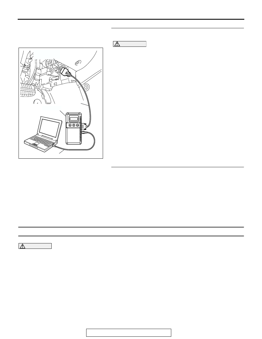
(1) Connect scan tool MB991958 to the data link connector.
(2) Turn the ignition switch to the "ON" position.
(3) Set scan tool MB991958 to the data reading mode for item
25, Barometric Pressure Sensor.
• When altitude is 0 m (0 foot), 101 kPa (29.8 In.Hg).
• When altitude is 600 m (1,969 feet), 95 kPa (28.1
In.Hg).
• When altitude is 1,200 m (3,937 feet), 88 kPa (26.0
In.Hg).
• When altitude is 1,800 m (5,906 feet), 81 kPa (23.9
In.Hg).
(4) Turn the ignition switch to the "LOCK" (OFF) position.
Q: Is the sensor operating properly?
YES : It can be assumed that this malfunction is intermittent.
Refer to GROUP 00, How to Use
Troubleshooting/Inspection Service Points
NO : Replace the PCM, then go to Step 2.
STEP 2. Test the OBD-II drive cycle.
(1) Carry out a test drive with the drive cycle pattern. Refer to
Diagnostic Function
− OBD-II Drive Cycle − Procedure 6 −
Other Monitor
(2) Check the diagnostic trouble code (DTC).
Q: Is DTC P2229 set?
YES : Retry the troubleshooting.
NO : The inspection is complete.
DTC U1073: Bus Off
CAUTION
• If the PCM output the DTC U1073, make sure
to diagnose the CAN bus line.
• Before replacing the ECU, make sure that the
communication circuit is operating normally.
.
DTC SET CONDITIONS
Check Conditions
• Always
Judgement Criteria
• Bus off error detected
.
TROUBLESHOOTING HINTS (The most likely
causes for this code to be set are:)
• CAN line harness damage or connector damage.
• PCM failed.
AC305412
AB
MB991910
DATA LINK
CONNECTOR
MB991824
MB991827