Mitsubishi Galant (2004+). Manual - part 1303


  Index      Mitsubishi     Mitsubishi Galant - service repair manual 2004 year


Search            


Content   ..  1301  1302  1303  1304   ..


Mitsubishi Galant (2004+). Manual - part 1303


MULTIPORT FUEL INJECTION (MFI) DIAGNOSIS

TSB Revision

MULTIPORT FUEL INJECTION (MFI) <3.8L ENGINE>

13B-905

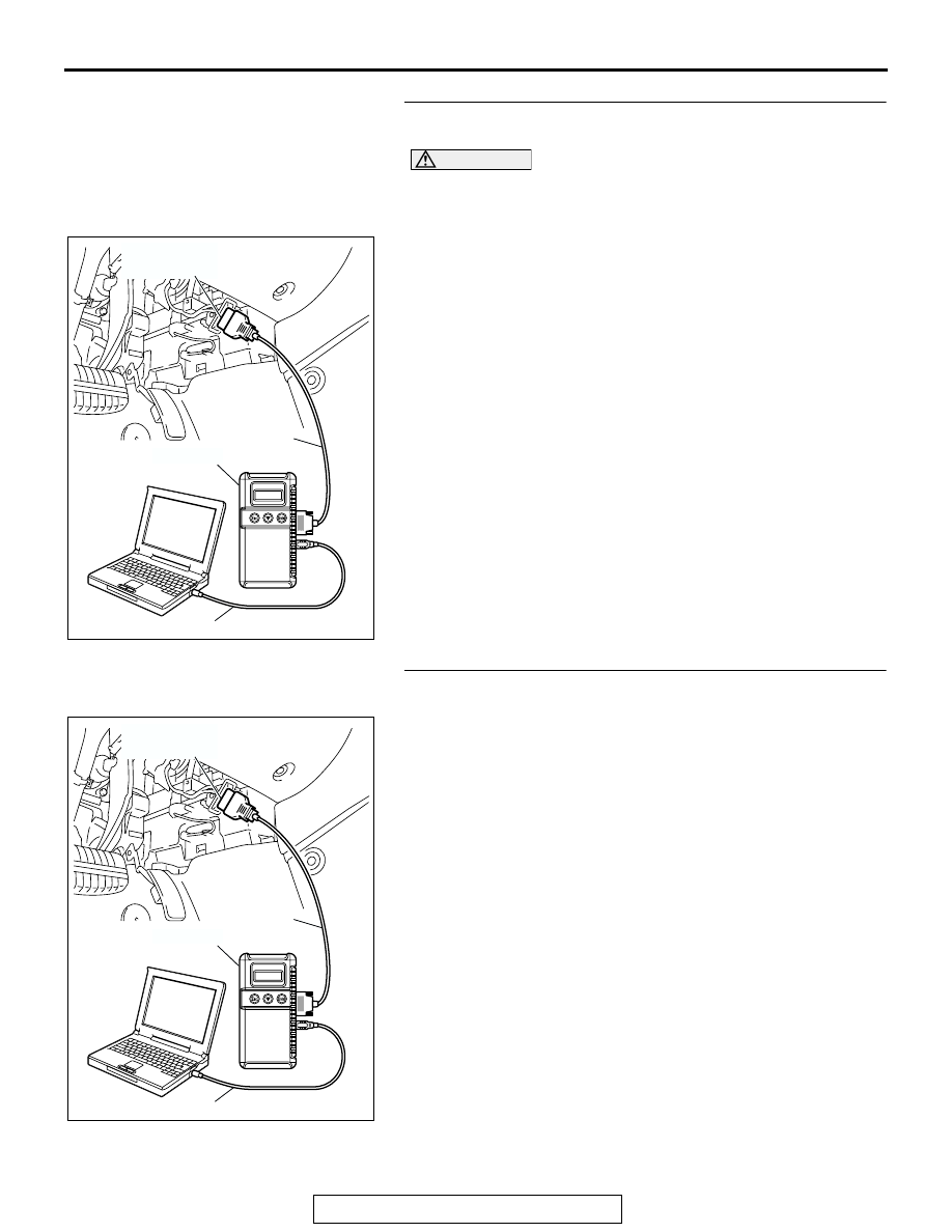
STEP 7. Using scan tool MB991958, check data list item 78: 
Accelerator Pedal Position Sensor (main).

CAUTION

To prevent damage to scan tool MB991958, always turn the 
ignition switch to the "LOCK"(OFF) position before con-
necting or disconnecting scan tool MB991958.
(1) Connect scan tool MB991958 to the data link connector.
(2) Turn the ignition switch to the "ON" position.
(3) Set scan tool MB991958 to the data reading mode for item 

78, Accelerator Pedal Position Sensor (main).

• Output voltage is between 0.7 and 1.3 volts when foot is 

released from accelerator pedal.

• Output voltage is 4.0 volts or higher when accelerator 

pedal is fully depressed.

(4) Turn the ignition switch to the "LOCK"(OFF) position.
Q: Is the sensor operating properly?

YES : It can be assumed that this malfunction is intermittent. 

Refer to GROUP 00, How to Use 
Troubleshooting/Inspection. Service Points 

P.00-6

.

NO :  Replace the PCM. Then go to Step 8.

STEP 8. Using scan tool MB991958, read the diagnostic 
trouble code (DTC).

(1) Connect scan tool MB991958 to the data link connector.
(2) Turn the ignition switch to the "ON" position.

(3) After the DTC has been deleted, read the DTC again.
(4) Turn the ignition switch to the "LOCK"(OFF) position.
Q: Is DTC P2123 set?

YES : Retry the troubleshooting.
NO :  The inspection is complete.

AC305412

AB

MB991910

DATA LINK

CONNECTOR

MB991824

MB991827

AC305412

AB

MB991910

DATA LINK

CONNECTOR

MB991824

MB991827

MULTIPORT FUEL INJECTION (MFI) DIAGNOSIS

TSB Revision

MULTIPORT FUEL INJECTION (MFI) <3.8L ENGINE>

13B-906

DTC P2127: Accelerator Pedal Position Sensor (sub) Circuit Low Input

CAUTION

If DTC P2127 has been set, TCL related DTC 
U1120 is also set. After P2127 has been diag-
nosed, don't forget to erase DTC U1120.

.

AK302873

YELLO

W

-RED

PINK-GREEN

BR

O

W

N

5 V

21

4

ACCELERATOR PEDAL 

POSITION SENSOR (SUB)

HALL IC

POWERTRAIN CONTROL 
MODULE (PCM)

27

22

6

5

Accelerator Pedal Position Sensor (sub) Circuit

B-20

C-24

6

1 2 3 4 5

22

21

23 24 25

26 27 28 29

30 31 32 33 34

35 36 37 38

39 40 41 42 43

AK303201

ACCELERATOR
PERAL

AB

CONNECTOR: C-24

C-24 (B)

ACCELERATOR 
PEDAL POSITION 
SENSOR

AK303085

CONNECTOR: B-20

PCM

AB

AIR CLEANER

B-20

MULTIPORT FUEL INJECTION (MFI) DIAGNOSIS

TSB Revision

MULTIPORT FUEL INJECTION (MFI) <3.8L ENGINE>

13B-907

CIRCUIT OPERATION

• A 5-volt power supply is applied on the accelera-

tor pedal position sensor (sub) power terminal 
(terminal No. 4) from the PCM (terminal No. 21).
The ground terminal (terminal No. 5) is grounded 
with PCM (terminal No. 22).

.

TECHNICAL DESCRIPTION

• The accelerator pedal position sensor (sub) out-

puts voltage which corresponds to the accelera-
tor pedal depression.

• The PCM checks whether the voltage is within a 

specified range.

.

DESCRIPTIONS OF MONITOR METHODS
Accelerator pedal position sensor (sub) output volt-

age is out of specified range.

.

MONITOR EXECUTION
Continuous

.

MONITOR EXECUTION CONDITIONS (Other 
monitor and Sensor)

Other Monitor (There is no temporary DTC stored 

in memory for the item monitored below)

• Not applicable

Sensor (The sensor below is determined to be 

normal)

• Not applicable

.

DTC SET CONDITIONS

Logic Flow Chart

.

START

END

NO

NO

YES

YES

MALFUNCTION

GOOD

CONTINUOUS

FAILURE FOR 0.3sec

OUTPUT VOLTAGE < 0.2V

AK302412

MULTIPORT FUEL INJECTION (MFI) DIAGNOSIS

TSB Revision

MULTIPORT FUEL INJECTION (MFI) <3.8L ENGINE>

13B-908

Check Conditions

• Ignition switch is "ON" position.

Judgement Criteria

• Accelerator pedal position sensor (sub) output 

voltage is 0.2 volt or less for 0.3 second.

.

OBD-II DRIVE CYCLE PATTERN
None.

.

TROUBLESHOOTING HINTS (The most likely 
causes for this code to be set are:)

• Accelerator pedal position sensor failed.

• Open or shorted accelerator pedal position sen-

sor (sub) circuit, harness damage or connector 
damage.

• PCM failed.

DIAGNOSIS

Required Special Tools:

• MB991958: Scan tool (MUT-III Sub Assembly)

• MB991824: V.C.I.

• MB991827: USB Cable

• MB991910: Main Harness A

STEP 1. Using scan tool MB991958, check data list item 77: 
Accelerator Pedal Position Sensor (sub).

CAUTION

To prevent damage to scan tool MB991958, always turn the 
ignition switch to the "LOCK"(OFF) position before con-
necting or disconnecting scan tool MB991958.
(1) Connect scan tool MB991958 to the data link connector.
(2) Turn the ignition switch to the "ON" position.

(3) Set scan tool MB991958 to the data reading mode for item 

77, Accelerator Pedal Position Sensor (sub).

• Output voltage is between 0.4 and 1.0 volts when foot is 

released from accelerator pedal.

• Output voltage is 3.7 volts or higher when accelerator 

pedal is fully depressed.

(4) Turn the ignition switch to the "LOCK"(OFF) position.
Q: Is the sensor operating properly?

YES : It can be assumed that this malfunction is intermittent. 

Refer to GROUP 00, How to Use 
Troubleshooting/Inspection Service Points 

P.00-6

.

NO :  Go to Step 2.

AC305412

AB

MB991910

DATA LINK

CONNECTOR

MB991824

MB991827


Content   ..  1301  1302  1303  1304   ..