Mitsubishi Galant (2004+). Manual - part 1285


  Index      Mitsubishi     Mitsubishi Galant - service repair manual 2004 year


Search            


Content   ..  1283  1284  1285  1286   ..


Mitsubishi Galant (2004+). Manual - part 1285


MULTIPORT FUEL INJECTION (MFI) DIAGNOSIS

TSB Revision

MULTIPORT FUEL INJECTION (MFI) <3.8L ENGINE>

13B-833

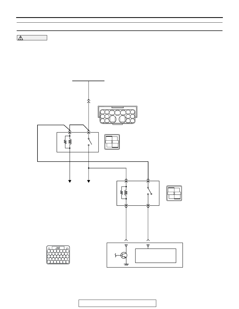
P0657 Throttle Actuator Control Motor Relay Circuit Malfunction

CAUTION

If DTC P0657 has been set, TCL related DTC 
U1120 is also set. After P0657 has been diag-
nosed, don't forget to erase DTC U1120.

1 2

3 4 5

14

15

8 9

12 13

6 7

10 11
16 17

1

2

3

4

AK302868

THROTTEL
ACTUATOR
CONTROL
MOTOR
RELAY

POWER SUPPLY

B-17X

B-14X

A-13

(MU802611)

BLUE-WHITE

RED-

WHITE

RED-

WHITE

RED-

WHITE

RED-
WHITE

RED-BLUE

To PCM

To PCM

MFI
RELAY

RED

RED

RED

FUSIBLE LINK(5)

2

1

5

3

4

2

1

3

4

123

122

1

2

3

4

POWERTRAIN
CONTROL
MODULE

B-23

1

2

3

4

121 122 123 124 125 126 127

128 129 130 131 132 133

134 135 136 137 138 139 140

141 142 143 144 145 146

147 148 149 150 151 152 153

MULTIPORT FUEL INJECTION (MFI) DIAGNOSIS

TSB Revision

MULTIPORT FUEL INJECTION (MFI) <3.8L ENGINE>

13B-834

.

CIRCUIT OPERATION

• Battery positive voltage is applied to the throttle 

actuator control motor relay terminal (terminal 
No. 1).

• Battery positive voltage is applied to the throttle 

actuator control motor relay terminal (terminal 
No. 2) from the MFI relay (terminal No. 1).

• PCM (terminal No. 123) applies current to the 

throttle actuator control motor relay coil by turning 
ON the power transistor in the unit in order to turn 
the relay ON.

• When the throttle actuator control motor relay 

turns ON, battery positive voltage is supplied by 
the throttle actuator control motor relay (terminal 
No. 1) to the PCM (terminal No. 122).

.

TECHNICAL DESCRIPTION

• When the ignition switch ON signal is input into 

the PCM, the PCM turns ON the throttle actuator 
control motor relay.

.

DTC SET CONDITIONS

Check Condition

• Ignition switch "ON" position.

Judgement Criteria

• The power line voltage of the electronic controlled 

throttle system should be 4.0 volts or less for 1.0 
seconds.

.

AK303148

CONNECTOR: A-13

AB

A-13(GR)

1

2

3

4

1

2

3

4

1

2

3

4

1

2

3

4

AK303014

CONNECTOR: B-17X

MFI RELAY

MFI RELAY

FRONT OF VEHICLE

B-17X

AB

1

2

3

4

1

2

3

4

1

2

3

4

1

2

3

4

AK303173

CONNECTOR: B-14X

MFI RELAY

MFI RELAY

FRONT OF VEHICLE

B-14X

AB

AK303059

CONNECTOR: B-23

PCM

AB

AIR CLEANER

B-23

MULTIPORT FUEL INJECTION (MFI) DIAGNOSIS

TSB Revision

MULTIPORT FUEL INJECTION (MFI) <3.8L ENGINE>

13B-835

TROUBLESHOOTING HINTS (The most likely 
causes for this code to be set are:)

• Throttle actuator control motor relay failed or mal-

adjusted.

• Open or shorted throttle actuator control motor 

relay circuit, or loose connector.

• PCM failed.

DIAGNOSIS

Required Special Tools:

• MB991958: Scan tool (MUT-III Sub Assembly)

• MB991824: V.C.I.

• MB991827: USB Cable

• MB991910: Main Harness A

STEP 1. Check harness connector B-14X at throttle 
actuator control motor relay for damage.

Q: Is the harness connector in good condition?

YES : Go to Step 2.
NO :  Repair or replace it. Refer to GROUP 00E, Harness 

Connector Inspection 

P.00E-2

. Then go to Step 14.

1

2

3

4

AK303175

CONNECTOR: B-14X

FRONT OF VEHICLE

B-14X

AB

HARNESS
CONNECTOR:
COMPONENT SIDE

RELAY BOX

MULTIPORT FUEL INJECTION (MFI) DIAGNOSIS

TSB Revision

MULTIPORT FUEL INJECTION (MFI) <3.8L ENGINE>

13B-836

STEP 2. Check the throttle actuator control motor relay.

CAUTION

Because it is not possible to distinguish the top and the 
bottom of the throttle actuator control motor relay, inspect 
with the triangle mark printed on the relay facing upward.
(1) Remove the throttle actuator control motor relay.

(2) Check for continuity between the throttle actuator control 

motor relay terminal No. 2 and No. 3.

• There should be continuity (approximately 70 ohms).

(3) Use jumper wires to connect throttle actuator control motor 

relay terminal No. 2 to the positive battery terminal and 
terminal No. 3 to the negative battery terminal.

(4) Check the continuity between the throttle actuator control 

motor relay terminal No. 1 and No. 4 while connecting and 
disconnecting the jumper wire at the negative battery 
terminal.

• Should be less than 2 ohms. (Negative battery terminal 

connected.)

• Should be open loop. (Negative battery terminal discon-

nected.)

(5) Install the throttle actuator control motor relay.
Q: Is the resistance normal?

YES : Go to Step 3.
NO :  Replace the throttle actuator control motor relay.       

Then go to Step 14.

1

2

3

4

AK303175

CONNECTOR: B-14X

FRONT OF VEHICLE

B-14X

AB

HARNESS
CONNECTOR:
COMPONENT SIDE

RELAY BOX

AK303205

1

2

3

4

AB

THROTTLE ACTUATOR 
CONTROL MOTOR RELAY
SIDE CONNECTOR

1

2

3

4

AK303193

THROTTLE ACTUATOR 
CONTROL MOTOR RELAY
SIDE CONNECTOR

AE


Content   ..  1283  1284  1285  1286   ..