Content .. 1271 1272 1273 1274 ..
Mitsubishi Galant (2004+). Manual - part 1273
MULTIPORT FUEL INJECTION (MFI) DIAGNOSIS
TSB Revision
MULTIPORT FUEL INJECTION (MFI) <3.8L ENGINE>
13B-785
DTC SET CONDITIONS
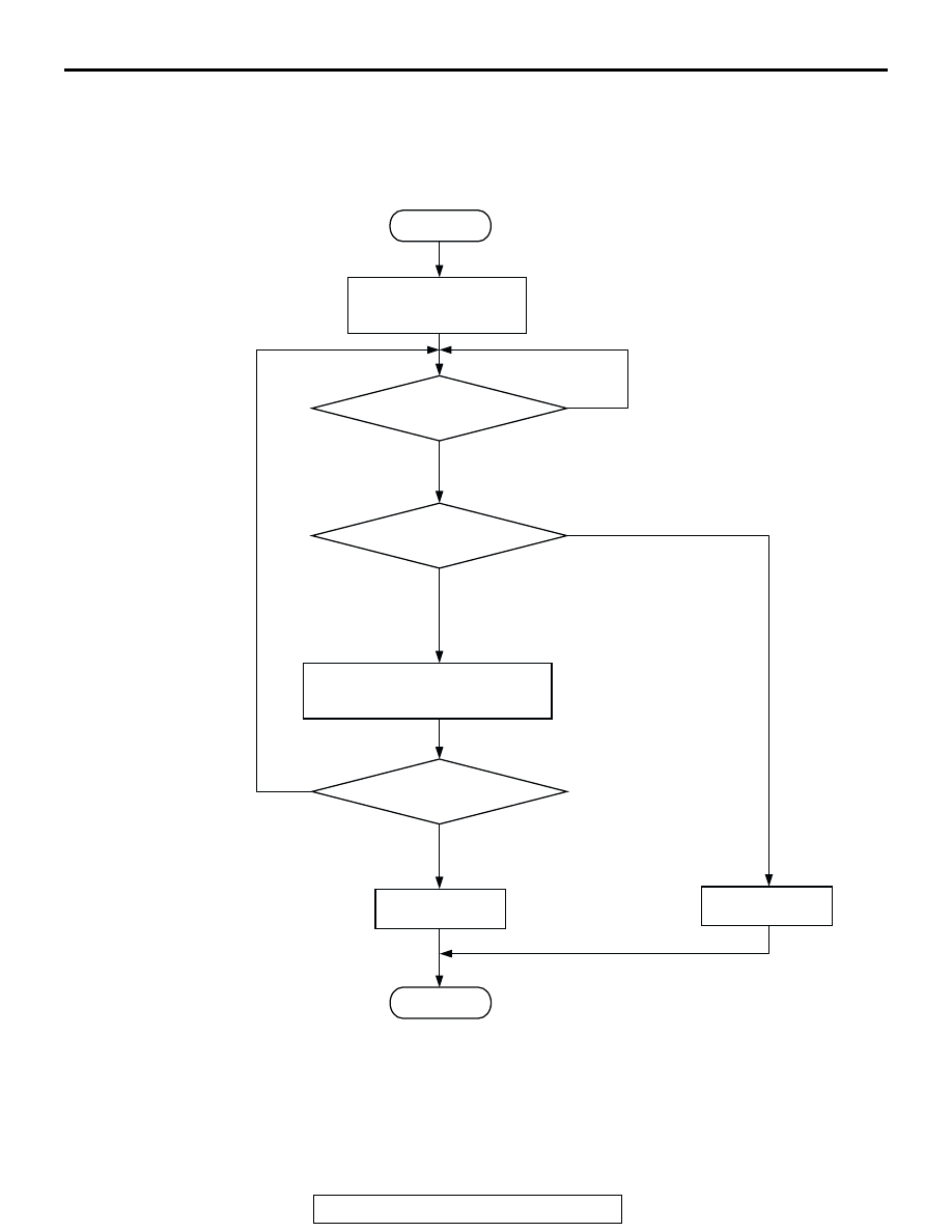
Logic Flow Chart
.
INDICATED FUEL LEVEL
CHANGE < 2L
ACCUMULATE FUEL CONSUMPTION
THROUGH FUEL INJECTORS.
ACCUMULATED FUEL
CONSUMPTION WILL NOT
RESET WHEN KEY-OFF/ON.
ACCUMULATED FUEL
CONSUMPTION > =30L
START
END
NO
NO
NO
YES
YES
YES
MALFUNCTION
GOOD
MONITORING
CONDITIONS
RESET ACCUMULATE
FUEL CONSUMPTION.
AK302407