Mitsubishi Galant (2004+). Manual - part 1268


  Index      Mitsubishi     Mitsubishi Galant - service repair manual 2004 year


Search            


Content   ..  1266  1267  1268  1269   ..


Mitsubishi Galant (2004+). Manual - part 1268


MULTIPORT FUEL INJECTION (MFI) DIAGNOSIS

TSB Revision

MULTIPORT FUEL INJECTION (MFI) <3.8L ENGINE>

13B-765

STEP 10. Check for leaks in evaporative emission hoses K 
and L.

Use a hand vacuum pump to test each hose K and L.

Q: Do the hoses hold vacuum?

YES :  Go to Step 11.
NO :  Replace any damaged hose. Then go to Step 19.

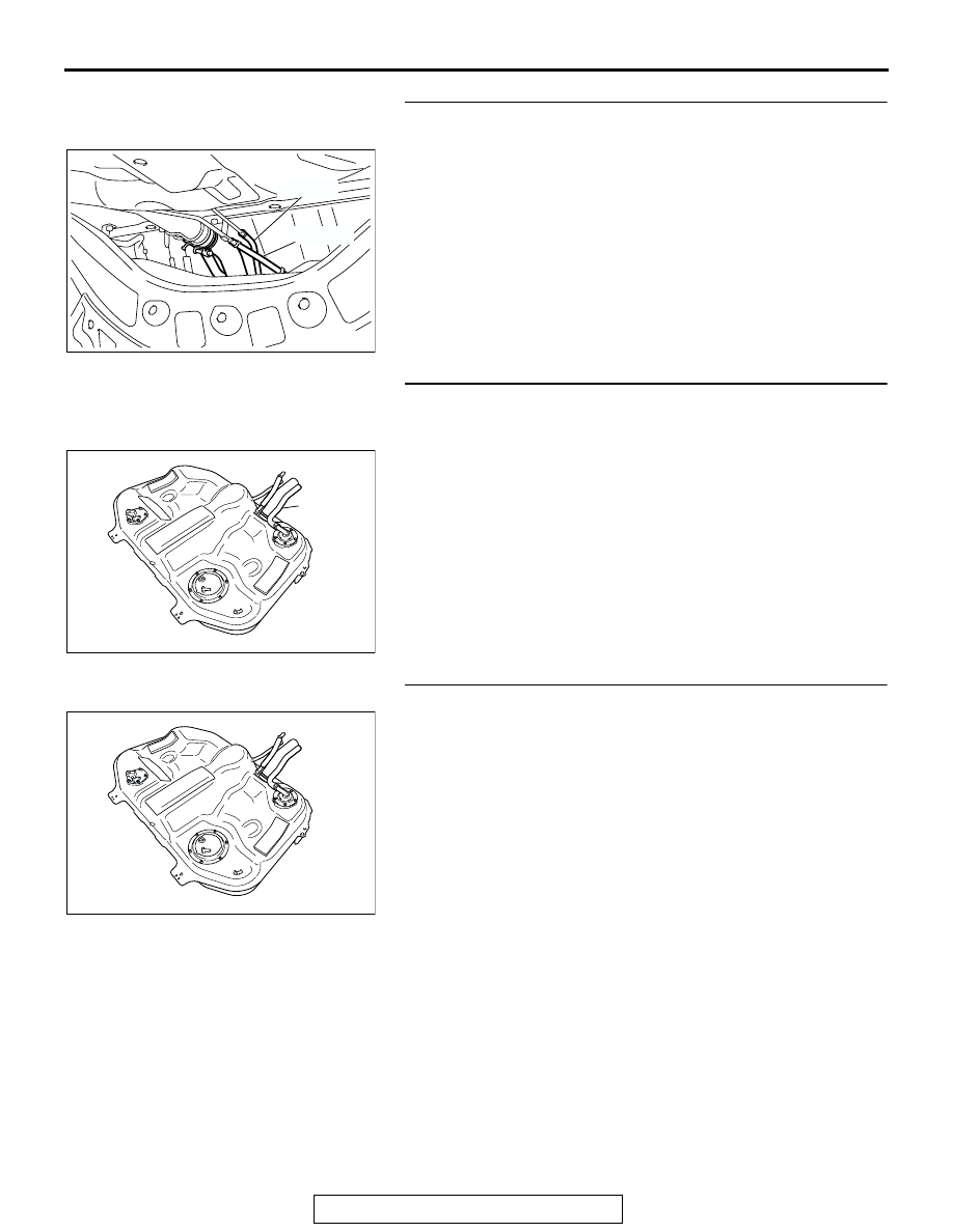
STEP 11. Check for leaks in evaporative emission hose M.
(1) Remove the fuel tank assembly (Refer to GROUP 13C, 

Fuel Tank 

P.13C-10

).

(2) Use the hand vacuum pump to check the hose M.
Q: Is the hose hold vacuum?

YES :  Go to Step 12.
NO :  Replace the hose and reinstall the fuel tank assembly 

(Refer to GROUP 13C, Fuel Tank 

P.13C-10

). Then go 

to Step 19.

STEP 12. Check for leaks in the fuel tank.

(1) Visually check for cracks or other leaks in the fuel tank.

NOTE: Carefully check the fuel pump module and the fuel 
tank differential pressure sensor installation in the fuel tank.

AC306776

AC

HOSE L

HOSE K

AC305683AC

HOSE M

AC305683

MULTIPORT FUEL INJECTION (MFI) DIAGNOSIS

TSB Revision

MULTIPORT FUEL INJECTION (MFI) <3.8L ENGINE>

13B-766

(2) Connect the evaporative emission system pressure pump  

(Miller number 6872A) to the fuel filler hose.

(3) Plug the hose and the nipple shown in the illustration.

NOTE: If these items are not securely plugged now, the fuel 
could leak in the next step.

(4) Pressurize the fuel tank with the evaporative emission 

system pressure pump.

(5) In the pressurized state, check for leaks by applying a 

soapy water solution to each section and look for bubbles.

Q: Are any leaks found?

YES <When there is a leak from the attachment points of 
the fuel pump module, fuel tank differential pressure 
sensor, fuel level sensor (sub) or leveling valve.> : 

Reassemble the leaked parts and check again that 
there are no leaks. Then reinstall the fuel tank (Refer 
to GROUP 13C, Fuel Tank 

P.13C-10

). Then go to 

Step 19   .

YES <When there is a leak from the fuel tank.> : Replace 

the fuel tank (Refer to GROUP 13C, Fuel Tank 

P.13C-10

). Go to Step 19.

NO :  When there is no leak, reinstall the fuel tank (Refer to 

GROUP 13C, Fuel Tank 

P.13C-10

). Then go to Step 

18.

AC305684

FUEL FILLER HOSE

AB

AC305684AC

MULTIPORT FUEL INJECTION (MFI) DIAGNOSIS

TSB Revision

MULTIPORT FUEL INJECTION (MFI) <3.8L ENGINE>

13B-767

STEP 13. Check for clogging in evaporative emission 
system hoses H through J.

(1) Remove the fuel tank filler tube protector (Refer to GROUP 

13C, Fuel Tank 

P.13C-10

).

(2) Use a hand vacuum pump on each hose from hoses H to J.
Q: Are the hoses in good condition?

YES : Go to Step 14.
NO :  Replace the damaged hose, and the fuel tank filler 

tube protector (Refer to GROUP 13C, Fuel Tank 

P.13C-10

). Then go to Step 19.

STEP 14. Test check valve.

(1) Check valve is a one-way check valve.

(2) Check valve should allow air to flow in only one direction.
Q: Does check valve allow air to pass in one direction  

only?
YES : 
Go to Step 15.
NO :  Replace check valve, and reinstall the fuel tank filler 

tube protector (Refer to GROUP 13C, Fuel Tank 

P.13C-10

). Then go to Step 19.

AC306401

HOSE H

AE

AC306800

AC

HOSE I

HOSE J

AC306800

AD

CHECK VALVE

AC306332

AB

CHECK VALVE

MULTIPORT FUEL INJECTION (MFI) DIAGNOSIS

TSB Revision

MULTIPORT FUEL INJECTION (MFI) <3.8L ENGINE>

13B-768

STEP 15. Check for clogging in evaporative emission 
hoses K and L.

Use a hand vacuum pump to test each hose K and L.

Q: Are the hoses in good condition?

YES :  Go to Step 16.
NO :  Replace any damaged hose. Then go to Step 19.

STEP 16. Check the evaporative emission canister for 
leaks and clogging.
(1) Remove the evaporative emission canister (Refer to 

GROUP 17, Evaporative Emission Canister and Fuel Tank 

Pressure Relief Valve 

P.17-97

).

(2) Connect a hand vacuum pump to the evaporative emission 

canister and plug the other nipples.

(3) Apply a pressure on the hand vacuum pump, and confirm 

that air is maintained.

(4) When the plugs are removed, check for air leakage.
(5) Disconnect the hand vacuum pump and install the 

evaporative emission canister (Refer to GROUP 17, 
Evaporative Emission Canister and Fuel Tank Pressure 
Relief Valve 

P.17-97

).

Q: Is the evaporative emission canister in good condition?

YES : Go to Step 17.
NO :  Replace the evaporative emission canister (Refer to 

GROUP 17, Evaporative Emission Canister and Fuel 
Tank Pressure Relief Valve 

P.17-97

). Then go to Step 

19   .

STEP 17. Check for clogging in evaporative emission hose 
M.
(1) Remove the fuel tank assembly (Refer to GROUP 13C, 

Fuel Tank 

P.13C-10

).

(2) Use the hand vacuum pump to check the hose M.
Q: Is the hose in good condition?

YES :  Reinstall the fuel tank assembly (Refer to GROUP 

13C, Fuel Tank 

P.13C-10

). Then go to Step 18.

NO :  Replace any damaged hose and reinstall the fuel tank 

assembly (Refer to GROUP 13C, Fuel Tank 

P.13C-10

). Then go to Step 19.

AC306776

AC

HOSE L

HOSE K

AC305682

AB

PLUGS

AC305683AC

HOSE M


Content   ..  1266  1267  1268  1269   ..