Mitsubishi Galant (2004+). Manual - part 1252


  Index      Mitsubishi     Mitsubishi Galant - service repair manual 2004 year


Search            


Content   ..  1250  1251  1252  1253   ..


Mitsubishi Galant (2004+). Manual - part 1252


MULTIPORT FUEL INJECTION (MFI) DIAGNOSIS

TSB Revision

MULTIPORT FUEL INJECTION (MFI) <3.8L ENGINE>

13B-701

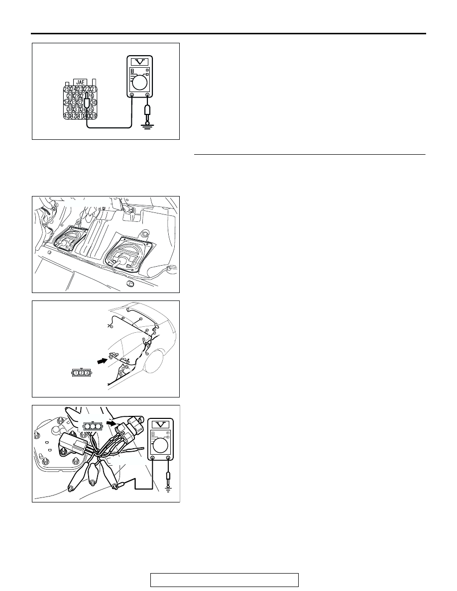
(5) Measure the voltage between terminal 22 and ground.

• The voltage should measure 0.5 volt or less.

(6) Install the fuel cap.
(7) Turn the ignition switch to the "LOCK" (OFF) position.
Q: Is the measured voltage 0.5 volt or less?

YES : Go to Step 6.
NO :  Go to Step 9.

STEP 6. Measure the signal voltage at intermediate 
connector D-23. 
(1) Remove the rear seat cushion assembly (Refer to GROUP 

52A, Rear Seat 

P.52A-30

).

(2) Remove the hole cover (RH).

(3) Disconnect fuel tank differential pressure sensor connector 

D-23.

(4) Use special tool MB991658 to connect terminals 1,2 and 3 

of  the fuel tank differential pressure sensor connector D-23.

(5) Turn the ignition switch to the "ON" position.
(6) Remove the fuel cap. 
(7) Measure the voltage between connector D-23 terminal 1 

and ground.

• The voltage should measure between 2.0 and 3.0 volts.

(8) Turn the ignition switch to the "LOCK" (OFF) position.
Q: Is the measured voltage between 2.0 and 3.0 volts?

YES : Go to Step 7.
NO :  Go to Step 15.

AC211193 AB

SPECIAL TOOL 23-PIN
CONNECTOR
(WITHOUT RED TAPE):
COMPONENT SIDE

AC306089

HOLE COVER

AB

AC305266

CONNECTOR: D-23

AB

D-23 (B)

AC306775

AB

MB991658

1 2 3

D-23 (B)


MULTIPORT FUEL INJECTION (MFI) DIAGNOSIS

TSB Revision

MULTIPORT FUEL INJECTION (MFI) <3.8L ENGINE>

13B-702

STEP 7. Check PCM connector B-20, intermediate 
connector C-25 and fuel tank differential pressure sensor 
connector D-23 for loose, corroded or damaged terminals, 
or terminals pushed back in the connector.

Q: Are the connectors and terminals in good condition?

YES : Go to Step 8.
NO :  Repair or replace the faulty components (Refer to 

GROUP 00E, Harness Connector Inspection 

P.00E-2

). Then go to Step 17.

AC306248

B-20 HARNESS

CONNECTOR:

COMPONENT SIDE

AB

B-20

CONNECTOR: B-20

PCM

AIR
CLEANER

AC305231

CONNECTOR: C-25

AM

C-25

AC305266

CONNECTOR: D-23

AB

D-23 (B)

MULTIPORT FUEL INJECTION (MFI) DIAGNOSIS

TSB Revision

MULTIPORT FUEL INJECTION (MFI) <3.8L ENGINE>

13B-703

STEP 8.  Check the harness wire between PCM connector 
B-20 terminal 23 and fuel tank differential pressure sensor 
connector D-23 terminal 1 for damage. 

Q: Is the harness wire in good condition?

YES : This malfunction is intermittent (Refer to GROUP 00, 

How to Use Troubleshooting/Inspection Service 
Points - How to Cope with Intermittent Malfunction 

P.00-6

). Go to Step 17.

NO :  Repair the damaged harness wire. Then go to Step 

17.

AC306248

B-20 HARNESS

CONNECTOR:

COMPONENT SIDE

AB

B-20

CONNECTOR: B-20

PCM

AIR
CLEANER

AC305266

CONNECTOR: D-23

AB

D-23 (B)

MULTIPORT FUEL INJECTION (MFI) DIAGNOSIS

TSB Revision

MULTIPORT FUEL INJECTION (MFI) <3.8L ENGINE>

13B-704

STEP 9. Measure the 5-volt reference signal at fuel tank 
differential pressure sensor connector D-23. 

(1) Remove the rear seat cushion assembly (Refer to GROUP 

52A, Rear Seat 

P.52A-30

).

(2) Remove the hole cover (RH).

(3) Disconnect fuel tank differential pressure sensor connector 

D-23.

(4) Use special tool MB991658 to connect terminals 1,2 and 3 

of  the fuel tank differential pressure sensor connector D-23.

(5) Turn the ignition switch to the "ON" position.
(6) Measure the voltage between  terminal 3 and ground.

• The voltage should measure between 4.9 and 5.1 volts.

(7) Turn the ignition switch to the "LOCK" (OFF) position.
Q: Is the measured voltage between 4.9 and 5.1 volts?

YES : Go to Step 12.
NO :  Go to Step 10.

AC306089

HOLE COVER

AB

AC305266

CONNECTOR: D-23

AB

D-23 (B)

AC306775

AB

MB991658

1 2 3

D-23 (B)


Content   ..  1250  1251  1252  1253   ..