Mitsubishi Galant (2004+). Manual - part 1247


  Index      Mitsubishi     Mitsubishi Galant - service repair manual 2004 year


Search            


Content   ..  1245  1246  1247  1248   ..


Mitsubishi Galant (2004+). Manual - part 1247


MULTIPORT FUEL INJECTION (MFI) DIAGNOSIS

TSB Revision

MULTIPORT FUEL INJECTION (MFI) <3.8L ENGINE>

13B-681

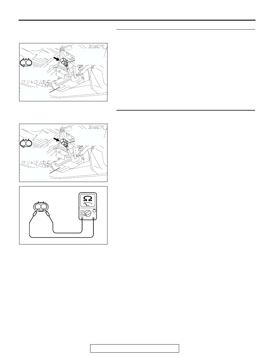
STEP 2. Check harness connector F-08 at the evaporative 
emission ventilation solenoid for damage.

Q: Is the harness connector in good condition?

YES : Go to Step 3.
NO :  Repair or replace it. Refer to GROUP 00E, Harness 

Connector Inspection 

P.00E-2

. Then go to Step 12.

STEP 3. Check the evaporative emission ventilation 
solenoid.

(1) Disconnect the evaporative emission ventilation solenoid 

connector F-08.

(2) Measure the resistance between evaporative emission 

ventilation solenoid side connector terminal No. 1 and No. 

2.

Standard value: 17 

 21 ohms [at 20°C (68°F)]

Q: Is the measured resistance between 17 and 21 ohms [at 

20

°C (68°F)]?

YES : Go to Step 4.
NO :  Replace it. Then go to Step 12.

1

2

AK303150

CONNECTOR: F-08

AB

EVAPORATIVE
EMISSION
VENTILATION
SOLENOID

EVAPORATIVE
EMISSION
CANISTER

F-08 (B)

HARNESS
CONNECTOR:
COMPONENT SIDE

1

2

AK303150

CONNECTOR: F-08

AB

EVAPORATIVE
EMISSION
VENTILATION
SOLENOID

EVAPORATIVE
EMISSION
CANISTER

F-08 (B)

HARNESS
CONNECTOR:
COMPONENT SIDE

1 2

AK202969

EVAPORATIVE EMISSION 
VENTILATION SOLENOID
CONNECTOR

AB

MULTIPORT FUEL INJECTION (MFI) DIAGNOSIS

TSB Revision

MULTIPORT FUEL INJECTION (MFI) <3.8L ENGINE>

13B-682

STEP 4. Measure the power supply voltage at evaporative 
emission ventilation solenoid harness side connector 
F-08.

(1) Disconnect the connector F-08 and measure at the harness 

side.

(2) Turn the ignition switch to the "ON" position.

(3) Measure the voltage between terminal No. 2 and ground.

• Voltage should be battery positive voltage.

(4) Turn the ignition switch to the "LOCK" (OFF) position.
Q: Is battery positive voltage (approximately 12 volts) 

present?
YES : 
Go to Step 6.
NO :  Go to Step 5.

STEP 5. Check harness connector B-17X at MFI relay for 
damage.

Q: Is the harness connector in good condition?

YES : Check connectors A-13 and C-25 at intermediate 

connector for damage, and repair or replace as 
required. Refer to GROUP 00E, Harness Connector 
Inspection 

P.00E-2

. If intermediate connectors are in 

good condition, repair harness wire between MFI 
relay connector B-17X (terminal No. 4) and 
evaporative emission ventilation solenoid connector 
F-08 (terminal No. 2) because of open circuit or short 
circuit to ground. Then go to Step 12.

NO :  Repair or replace it. Refer to GROUP 00E, Harness 

Connector Inspection 

P.00E-2

. Then go to Step 12.

1

2

AK303150

CONNECTOR: F-08

AB

EVAPORATIVE
EMISSION
VENTILATION
SOLENOID

EVAPORATIVE
EMISSION
CANISTER

F-08 (B)

HARNESS
CONNECTOR:
COMPONENT SIDE

1

2

AK303152

F-08 HARNESS 
CONNECTOR: 
COMPONENT SIDE

AB

1

2

3

4

AK303017

CONNECTOR: B-17X

FRONT OF VEHICLE

B-17X

AB

HARNESS
CONNECTOR:
COMPONENT SIDE

RELAY BOX

MULTIPORT FUEL INJECTION (MFI) DIAGNOSIS

TSB Revision

MULTIPORT FUEL INJECTION (MFI) <3.8L ENGINE>

13B-683

STEP 6. Measure the power supply voltage at PCM 
connector B-19 by using power plant ECU check harness 
special tool MB991923.

(1) Disconnect the all PCM connectors and connect power 

plant ECU check harness special tool MB991923 between 
the separated connectors.

(2) Turn the ignition switch to the "ON" position.

AK303153

4 3 2 1

7 6 5

9 8

11 10

14 13 12

18 17 16 15

CONNECTOR: B-19

PCM

AB

AIR CLEANER

HARNESS CONNECTOR: 
COMPONENT SIDE

B-19 (B)

AK202974

4 3 2 1

7 6 5

9 8

11 10

14 13 12

18 17 16 15

AB

POWER PLANT ECU 
CHECK HARNESS CONNECTOR

MB991923

PCM

MULTIPORT FUEL INJECTION (MFI) DIAGNOSIS

TSB Revision

MULTIPORT FUEL INJECTION (MFI) <3.8L ENGINE>

13B-684

(3) Measure the voltage between terminal No. 2 and ground.

• Voltage should be battery positive voltage.

(4) Turn the ignition switch to the "LOCK" (OFF) position.
Q: Is battery positive voltage (approximately 12 volts) 

present?
YES : 
Go to Step 9.
NO :  Go to Step 7.

STEP 7. Check harness connector B-19 at PCM for 
damage.

Q: Is the harness connector in good condition?

YES : Go to Step 8.
NO :  Repair or replace it. Refer to GROUP 00E, Harness 

Connector Inspection 

P.00E-2

. Then go to Step 12.

4 3 2 1

7 6 5

9 8

11 10

14 13 12

18 17 16 15

AK202975AB

POWER PLANT ECU 
CHECK HARNESS 
CONNECTOR 

AK303153

4 3 2 1

7 6 5

9 8

11 10

14 13 12

18 17 16 15

CONNECTOR: B-19

PCM

AB

AIR CLEANER

HARNESS CONNECTOR: 
COMPONENT SIDE

B-19 (B)


Content   ..  1245  1246  1247  1248   ..