Mitsubishi Galant (2004+). Manual - part 1186


  Index      Mitsubishi     Mitsubishi Galant - service repair manual 2004 year


Search            


Content   ..  1184  1185  1186  1187   ..


Mitsubishi Galant (2004+). Manual - part 1186


MULTIPORT FUEL INJECTION (MFI) DIAGNOSIS

TSB Revision

MULTIPORT FUEL INJECTION (MFI) <3.8L ENGINE>

13B-437

Check Conditions

• Engine coolant temperature is higher than 77°C 

(171

°F).

• Under the closed loop air/fuel ratio control.

Judgment Criteria

• Long-term fuel trim has continued to be −12.5 

percent for 5 seconds.

or

• Short-term fuel trim has continued to be −30.0 

percent for 5 seconds.

.

OBD-II DRIVE CYCLE PATTERN
Refer to Diagnostic Function 

− OBD-II Drive Cycle − 

Procedure 2 

− Fuel Trim Monito

P.13B-5

.

.

TROUBLESHOOTING HINTS (The most likely 

causes for this code to be set are:)

• Mass airflow sensor failed.

• Injector (Number 2, 4, 6) failed.

• Incorrect fuel pressure.

• Engine coolant temperature sensor failed.

• Intake air temperature sensor failed.

• Barometric pressure sensor failed.

• Manifold absolute pressure sensor failed.

• Harness damage in left bank injector circuit or 

connector damage.

• PCM failed.

DIAGNOSIS

Required Special Tools:

• MB991958: Scan Tool (MUT-III Sub Assembly)

• MB991824: V.C.I.

• MB991827: USB Cable

• MB991910: Main Harness A

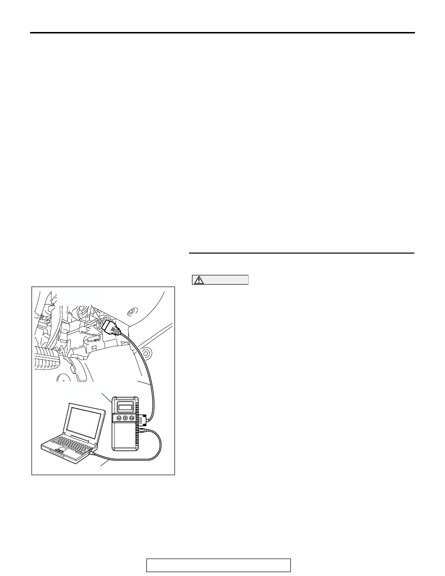
STEP 1. Using scan tool MB991958, check data list item 12: 
Mass Airflow Sensor.

CAUTION

To prevent damage to scan tool MB991958, always turn the 
ignition switch to the "LOCK" (OFF) position before con-
necting or disconnecting scan tool MB991958.
(1) Connect scan tool MB991958 to the data link connector.
(2) Start the engine and run at idle.

(3) Set scan tool MB991958 to the data reading mode for item 

12, Mass Airflow Sensor.

(4) Warm up the engine to normal operating temperature: 80

°C 

to 95

°C (176°F to 203°F).

• When idling, between 2.0 and 6.0 g/sec.

• When 2,500 r/min, between 8.0 and 16.0 g/sec.

(5) Turn the ignition switch to the "LOCK" (OFF) position.
Q: Is the sensor operating properly?

YES : YES: Go to Step 2.
NO :  Refer to, DTC P0101 

− Mass Airflow Circuit 

Range/Performance Problem 

P.13B-40

, DTC P0102 

− Mass Airflow Circuit Low Inpu

P.13B-51

, DTC 

P0103 

− Mass Airflow Circuit High Input 

P.13B-61

.

AC305412

AB

MB991910

DATA LINK

CONNECTOR

MB991824

MB991827

MULTIPORT FUEL INJECTION (MFI) DIAGNOSIS

TSB Revision

MULTIPORT FUEL INJECTION (MFI) <3.8L ENGINE>

13B-438

STEP 2. Using scan tool MB991958, check data list item 13: 
Intake Air Temperature Sensor.

(1) Turn the ignition switch to the "ON" position.
(2) Set scan tool MB991958 to the data reading mode for item 

13, Intake Air Temperature Sensor.

• The intake air temperature and temperature shown with 

the scan tool should approximately match.

(3) Turn the ignition switch to the "LOCK" (OFF) position.
Q: Is the sensor operating properly?

YES : Go to Step 3.
NO :  Refer to DTC P0111 

− Intake Air Temperature Circuit 

Range/Performance Problem 

P.13B-103

 DTC P0112 

− Intake Air Temperature Circuit Low Input 

P.13B-112

, DTC P0113 

− Intake Air Temperature 

Circuit High Input 

P.13B-119

.

STEP 3. Using scan tool MB991958, check data list item 21: 
Engine Coolant Temperature Sensor.

(1) Turn the ignition switch to the "ON" position.
(2) Set scan tool MB991958 to the data reading mode for item 

21, Engine Coolant Temperature Sensor.

• The engine coolant temperature and temperature 

shown with the scan tool should approximately match.

(3) Turn the ignition switch to the "LOCK" (OFF) position.
Q: Is the sensor operating properly?

YES : Go to Step 4.
NO :  Refer to DTC P0116 

− Engine Coolant Temperature 

Circuit Range/Performance Problem 

P.13B-129

, DTC 

P0117 

− Engine Coolant Temperature Circuit Low 

Input 

P.13B-138

, DTC P0118 

− Engine Coolant 

Temperature Circuit High Input 

P.13B-145

.

AC305412

AB

MB991910

DATA LINK

CONNECTOR

MB991824

MB991827

AC305412

AB

MB991910

DATA LINK

CONNECTOR

MB991824

MB991827

MULTIPORT FUEL INJECTION (MFI) DIAGNOSIS

TSB Revision

MULTIPORT FUEL INJECTION (MFI) <3.8L ENGINE>

13B-439

STEP 4. Using scan tool MB991958, check data list item 25: 
Barometric Pressure Sensor.

(1) Turn the ignition switch to the "ON" position.
(2) Set scan tool MB991958 to the data reading mode for item 

25, Barometric Pressure Sensor.

• When altitude is 0 m (0 foot), 101 kPa (29.8 in.Hg).

• When altitude is 600 m (1,969 feet), 95 kPa (28.1 in.Hg).

• When altitude is 1,200 m (3,937 feet), 88 kPa (26.0 

in.Hg).

• When altitude is 1,800 m (5,906 feet), 81 kPa. (23.9 

in.Hg)

(3) Turn the ignition switch to the "LOCK" (OFF) position.
Q: Is the sensor operating properly?

YES : Go to Step 5.
NO :  Refer to DTC P2227 

− Barometric Pressure Circuit 

Range/Performance Problem 

P.13B-943

, DTC P2228 

− Barometric Pressure Circuit Low Inpu

P.13B-945

DTC P2229 

− Barometric Pressure Circuit High Input 

P.13B-947

.

STEP 5. Using scan tool MB991958, check data list item 95: 
Manifold Absolute Pressure Sensor.

(1) Connect scan tool MB991958 to the data link connector.
(2) Turn the ignition switch to the "ON" position.

(3) Set scan tool MB991958 to the data reading mode for item 

95, Manifold Absolute Pressure Sensor.

• When altitude is 0 m (0 foot), 101 kPa (29.8 in.Hg).

• When altitude is 600 m (1,969 feet), 95 kPa (28.1 in.Hg).

• When altitude is 1,200 m (3,937 feet), 88 kPa (26.0 

in.Hg).

• When altitude is 1,800 m (5,906 feet), 81 kPa (23.9 

in.Hg).

(4) Start the engine.

• When the engine is idling, 16 − 36 kPa (4.7 − 10.6 

in.Hg).

• When the engine is suddenly revved, manifold absolute 

pressure varies.

(5) Turn the ignition switch to the "LOCK" (OFF) position.
Q: Is the sensor operating properly?

YES : Go to Step 6.
NO :  Refer to DTC P0106 

− Manifold Absolute Pressure 

Circuit Range / Performance Problem

P.13B-68

, DTC 

P0107 

− Manifold Absolute Pressure Circuit Low 

Input

P.13B-82

, DTC P0108 

−Manifold Absolute 

Pressure Circuit High Input

P.13B-94

.

AC305412

AB

MB991910

DATA LINK

CONNECTOR

MB991824

MB991827

AC305412

AB

MB991910

DATA LINK

CONNECTOR

MB991824

MB991827

MULTIPORT FUEL INJECTION (MFI) DIAGNOSIS

TSB Revision

MULTIPORT FUEL INJECTION (MFI) <3.8L ENGINE>

13B-440

STEP 6. Check the left bank injector.

(1) Disconnect the left bank injector connector B-30, B-27 ,

B-26.

(2) Measure the resistance between each injector side 

connector terminal No. 1 and No. 2.

Standard value: 10.5 

 13.5 ohms [at 20°C (68°F)]

Q: Is the measured resistance between 10.5 and 13.5 ohms 

[at 20

°C (68°F)]?

YES : Go to Step 7.
NO :  Replace the injector. Then go to Step 9.

STEP 7. Check the fuel pressure.

Refer to On-vehicle Service 

− Fuel Pressure Test 

P.13B-1133

.

Q: Is the fuel pressure normal?

YES : Repair it. Then go to Step 9.
NO :  Go to Step 8.

STEP 8. Replace the left bank injector.

(1) Replace the left bank injector.
(2) Carry out a test drive with the drive cycle pattern. Refer to 

Diagnostic Function 

− OBD-II Drive Cycle − Procedure 2 − 

Fuel Trim Monitor 

P.13B-5

.

(3) Check the diagnostic trouble code (DTC).
Q: Is DTC P0175 set?

YES : Replace the PCM. Then go to Step 9.
NO :  The inspection is complete.

AK303075

M

1

2

CONNECTOR: B-26, B-27, B-30

B-30 (GR)

B-27 (GR)

B-26 (GR)

HARNESS CONNECTOR:
COMPONENT SIDE

AB

AK000559

2

1

INJECTOR SIDE
CONNECTOR

AB

AK303075

M

1

2

CONNECTOR: B-26, B-27, B-30

B-30 (GR)

B-27 (GR)

B-26 (GR)

HARNESS CONNECTOR:
COMPONENT SIDE

AB


Content   ..  1184  1185  1186  1187   ..