Mitsubishi Galant (2004+). Manual - part 1177


  Index      Mitsubishi     Mitsubishi Galant - service repair manual 2004 year


Search            


Content   ..  1175  1176  1177  1178   ..


Mitsubishi Galant (2004+). Manual - part 1177


MULTIPORT FUEL INJECTION (MFI) DIAGNOSIS

TSB Revision

MULTIPORT FUEL INJECTION (MFI) <3.8L ENGINE>

13B-401

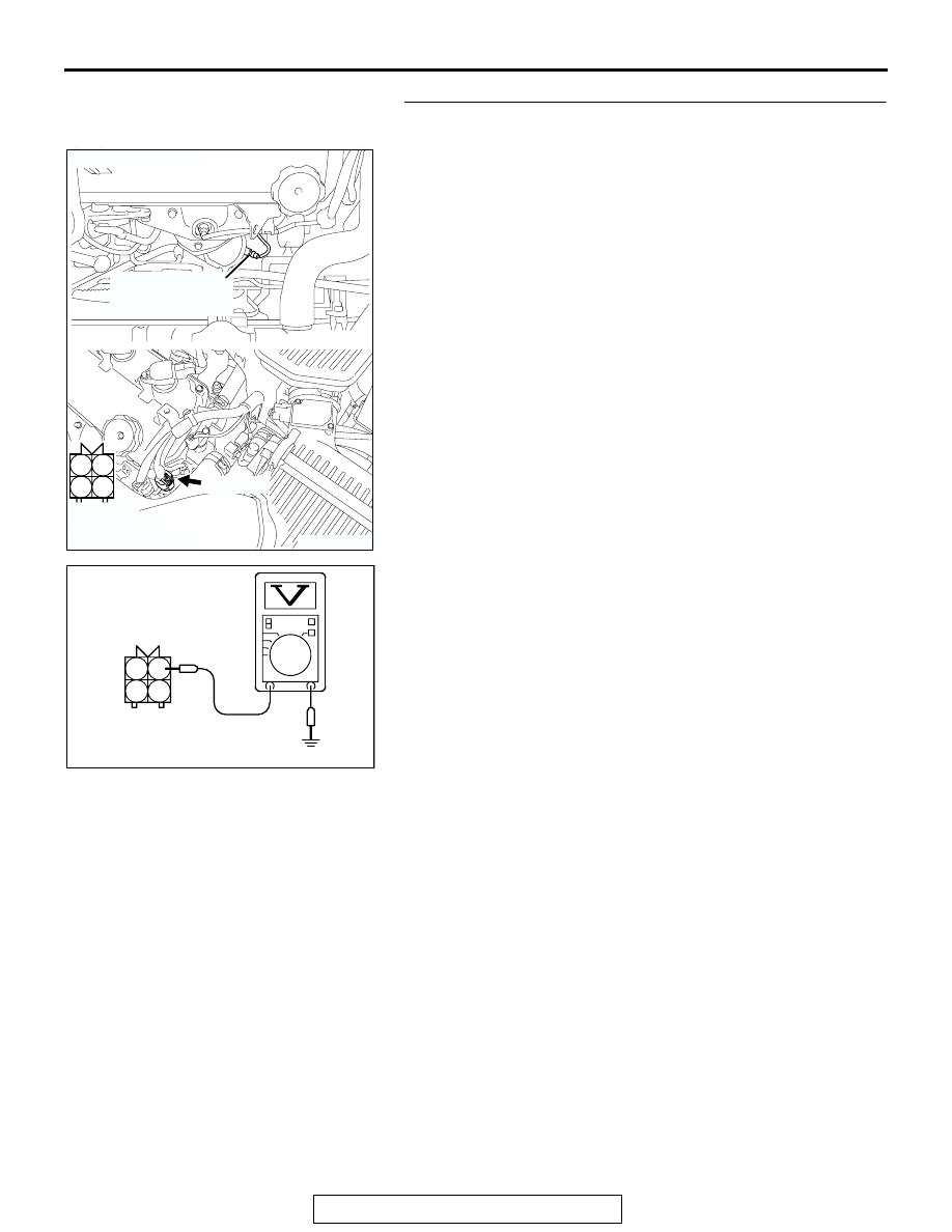
STEP 3. Measure the power supply voltage at left bank 
heated oxygen sensor (rear) harness side connector B-24.

(1) Disconnect the connector B-24 and measure at the harness 

side.

(2) Turn the ignition switch to the "ON" position.

(3) Measure the voltage between terminal No. 1 and ground.

• Voltage should be battery positive voltage.

(4) Turn the ignition switch to the "LOCK" (OFF) position.
Q: Is battery positive voltage (approximately 12 volts) 

present?
YES : 
Go to Step 5.
NO :  Go to Step 4.

1

2

3

4

AK303079

HARNESS
CONNECTOR:
COMPONENT SIDE

CONNECTOR: B-24

AB

LEFT BANK
HEATED OXYGEN
SENSOR (REAR)

B-24 (GR)

AKX01496

B-24 HARNESS 
CONNECTOR: 
COMPONENT SIDE

1

2

3

4

AT

MULTIPORT FUEL INJECTION (MFI) DIAGNOSIS

TSB Revision

MULTIPORT FUEL INJECTION (MFI) <3.8L ENGINE>

13B-402

STEP 4. Check harness connector B-17X at the MFI relay 
for damage.

Q: Is the harness connector in good condition?

YES : Repair harness wire between MFI relay connector 

B-17X (terminal No. 4) and left bank heated oxygen 
sensor (rear) connector B-24 (terminal No. 1) 
because of open circuit or short circuit to ground. 
Then go to Step 12.

NO :  Repair or replace it. Refer to GROUP 00E, Harness 

Connector Inspection 

P.00E-2

. Then go to Step 12.

1

2

3

4

AK303017

CONNECTOR: B-17X

FRONT OF VEHICLE

B-17X

AB

HARNESS
CONNECTOR:
COMPONENT SIDE

RELAY BOX

MULTIPORT FUEL INJECTION (MFI) DIAGNOSIS

TSB Revision

MULTIPORT FUEL INJECTION (MFI) <3.8L ENGINE>

13B-403

STEP 5. Measure the power supply voltage at PCM 
connector B-23 by using power plant ECU check harness 
special tool MB991923.

(1) Disconnect the all PCM connectors and connect power 

plant ECU check harness special tool MB991923 between 
the separated connectors.

(2) Turn the ignition switch to the "ON" position.

127 126 125 124 123 122 121

133 132 131 130 129 128

140 139 138 137 136 135 134

146 145 144 143 142 141

153 152 151 150 149 148 147

AK303058

HARNESS CONNECTOR: 
COMPONENT SIDE

CONNECTOR: B-23

B-23

PCM

AB

AIR CLEANER

AK202954

127 126 125 124 123 122 121

133 132 131 130 129 128

140 139 138 137 136 135 134

146 145 144 143 142 141

153 152 151 150 149 148 147

AB

POWER PLANT ECU 
CHECK HARNESS CONNECTOR

MB991923

PCM

MULTIPORT FUEL INJECTION (MFI) DIAGNOSIS

TSB Revision

MULTIPORT FUEL INJECTION (MFI) <3.8L ENGINE>

13B-404

(3) Measure the voltage between terminal No. 137 and ground.

• Voltage should be battery positive voltage.

(4) Turn the ignition switch to the "LOCK" (OFF) position.
Q: Is battery positive voltage (approximately 12 volts) 

present?
YES : 
Go to Step 8.
NO :  Go to Step 6.

STEP 6. Check harness connector B-23 at PCM for 
damage.

Q: Is the harness connector in good condition?

YES : Go to Step 7.
NO :  Repair or replace it. Refer to GROUP 00E, Harness 

Connector Inspection 

P.00E-2

. Then go to Step 12. 

127 126 125 124 123 122 121

133 132 131 130 129 128

140 139 138 137 136 135 134

146 145 144 143 142 141

153 152 151 150 149 148 147

AK203117AB

POWER PLANT ECU 
CHECK HARNESS 
CONNECTOR 

127 126 125 124 123 122 121

133 132 131 130 129 128

140 139 138 137 136 135 134

146 145 144 143 142 141

153 152 151 150 149 148 147

AK303058

HARNESS CONNECTOR: 
COMPONENT SIDE

CONNECTOR: B-23

B-23

PCM

AB

AIR CLEANER


Content   ..  1175  1176  1177  1178   ..