Mitsubishi Galant (2004+). Manual - part 1092


  Index      Mitsubishi     Mitsubishi Galant - service repair manual 2004 year


Search            


Content   ..  1090  1091  1092  1093   ..


Mitsubishi Galant (2004+). Manual - part 1092


MULTIPORT FUEL INJECTION (MFI) DIAGNOSIS

TSB Revision

MULTIPORT FUEL INJECTION (MFI) <3.8L ENGINE>

13B-61

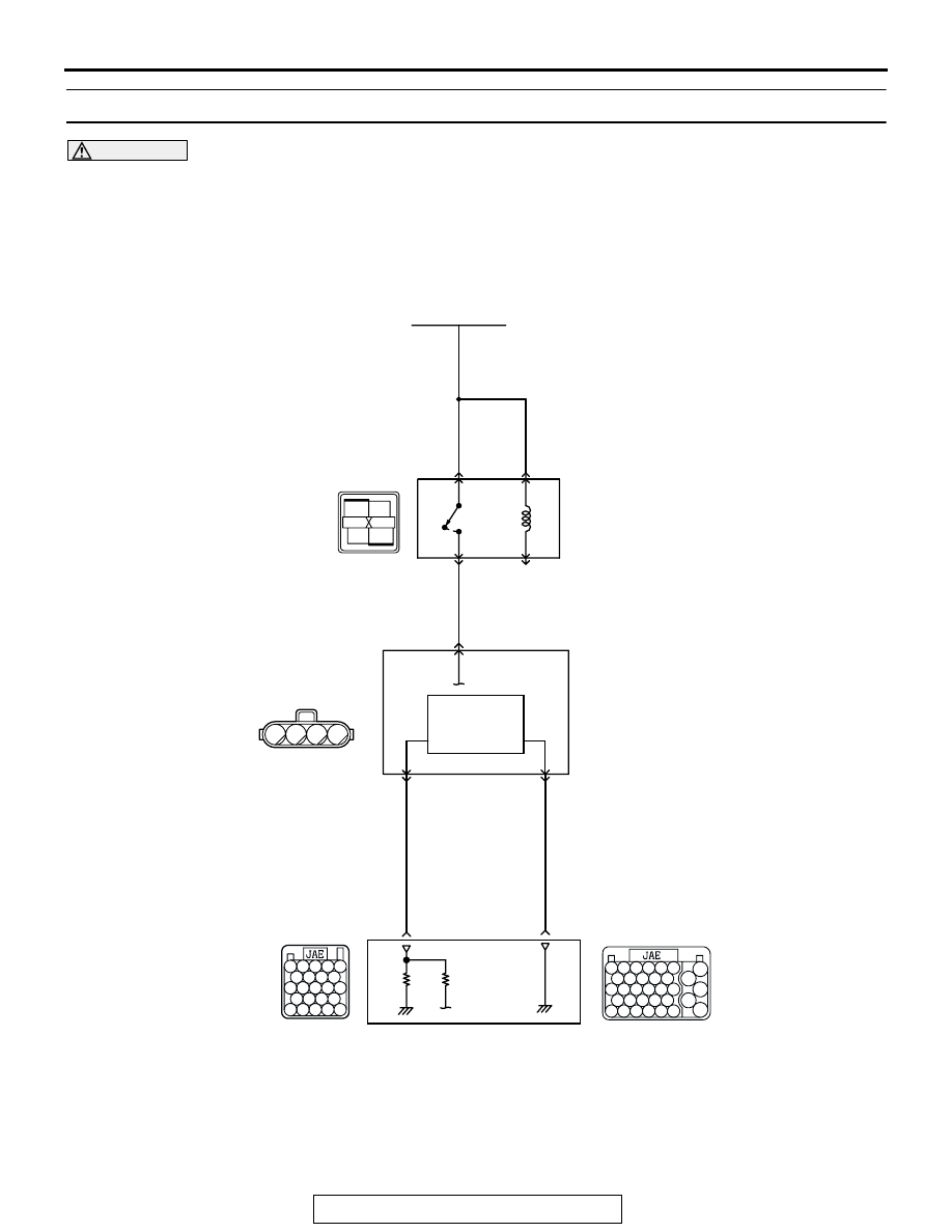
DTC P0103: Mass Airflow Circuit High Input

CAUTION

If DTC P0103 has been set, TCL related DTC 
U1120 is also set. After P0103 has been diag-
nosed, don't forget to erase DTC U1120.

RED

RED-

WHITE

RED-

WHITE

RED-

WHITE

AK302832

B-10

B-17X

MFI 
RELAY

BATTERY

MASS AIRFLOW 
SENSOR

2

1

2

4

3

Mass Airflow Sensor Circuit

1

2

3

4

1

2

3 4

WHITE-GREEN

BLA

CK

POWERTRAIN CONTROL 
MODULE (PCM)

108

3

69

4

B-22

B-21

HEAT
SENSITIZING
RESISTANCE

100

99

92

91

93 94 95

96 97 98

101 102 103 104

105 106 107 108

109 110 111 112 113

52

51

53 54 55 56

57

58 59 60 61 62

63

64 65 66 67 68 69

70

71 72 73 74 75

76

77 78 79 80 81 82

83

MULTIPORT FUEL INJECTION (MFI) DIAGNOSIS

TSB Revision

MULTIPORT FUEL INJECTION (MFI) <3.8L ENGINE>

13B-62

.

CIRCUIT OPERATION

• The mass airflow sensor power is supplied from 

the MFI relay (terminal No. 4), and the ground is 
provided on the PCM (terminal No. 69).

• 5-volt power is applied to the mass airflow sensor 

output terminal (terminal No. 3) from the PCM 
(terminal No. 108).

.

TECHNICAL DESCRIPTION

• While the engine is running, the mass airflow 

sensor outputs voltage which corresponds to the 
mass airflow rate.

• The PCM checks whether the voltage output by 

the mass airflow sensor while the engine is run-
ning is within a specified range.

.

DESCRIPTIONS OF MONITOR METHODS
Mass airflow sensor output voltage is out of specified 

range.

.

MONITOR EXECUTION
Continuous

.

MONITOR EXECUTION CONDITIONS (Other 
monitor and Sensor)

Other Monitor (There is no temporary DTC stored 

in memory for the item monitored below)

• Not applicable

Sensor (The sensor below is determined to be 

normal)

• Not applicable

.

1

2

3

4

1

2

3

4

1

2

3

4

1

2

3

4

AK303014

CONNECTOR: B-17X

MFI RELAY

MFI RELAY

FRONT OF VEHICLE

B-17X

AB

AK303012

CONNECTOR: B-10

MASS AIRFLOW SENSOR

AB

B-10 (GR)

AK303013

CONNECTORS: B-21, B-22

PCM

AB

AIR CLEANER

B-22 (B)

B-21 (B)

MULTIPORT FUEL INJECTION (MFI) DIAGNOSIS

TSB Revision

MULTIPORT FUEL INJECTION (MFI) <3.8L ENGINE>

13B-63

DTC SET CONDITIONS

Logic Flow Chart

.

Check Conditions

• 3 seconds or more have passed since the ignition 

switch was turned to "ON" position.

Judgement Criteria

• Mass airflow sensor output voltage has continued 

to be higher than 4.9 volts for 2 seconds.

.

OBD-II DRIVE CYCLE PATTERN
Refer to Diagnostic Function 

− OBD-II Drive Cycle − 

Procedure 6 

 Other Monitor 

P.13B-5

.

.

TROUBLESHOOTING HINTS (The most likely 
causes for this code to be set are:)

• Mass airflow sensor failed.

• Open mass airflow sensor circuit, or connector 

damage.

• PCM failed. 

END

MALFUNCTION

YES

YES

YES

NO

NO

NO

CONTINUOUS

FAILURE FOR 2secs

OUTPUT VOLTAGE

< 0.2V

OUTPUT VOLTAGE

> 4.9V

MONITORING

CONDITIONS

GOOD

START

AK302377

YES

NO

MULTIPORT FUEL INJECTION (MFI) DIAGNOSIS

TSB Revision

MULTIPORT FUEL INJECTION (MFI) <3.8L ENGINE>

13B-64

DIAGNOSIS

Required Special Tool:

• MB991958: Scan tool (MUT-III Sub Assembly)

• MB991824: V.C.I.

• MB991827: USB Cable

• MB991910: Main Harness A

STEP 1. Using scan tool MB991958, check data list item 12: 
Mass Airflow Sensor.

CAUTION

To prevent damage to scan tool MB991958, always turn the 
ignition switch to the "LOCK" (OFF) position before con-
necting or disconnecting scan tool MB991958.
(1) Connect scan tool MB991958 to the data link connector.
(2) Start the engine and run at idle.
(3) Set scan tool MB991958 to the data reading mode for item 

12, Mass Airflow Sensor.

(4) Warm up the engine to normal operating temperature: 80

°C 

to 95

°C (176°F to 203°F).

• The standard value during idling should be between 2.0 

and 6.0 g/sec.

• When the engine is revved, the mass airflow rate should 

increase according to the increase in engine speed.

(5) Turn the ignition switch to the "LOCK" (OFF) position.
Q: Is the sensor operating properly?

YES : It can be assumed that this malfunction is intermittent. 

Refer to GROUP 00, How to Use 
Troubleshooting/Inspection Service Points 

P.00-6

.

NO :  Go to Step 2.

STEP 2. Check harness connector B-10 at mass airflow 
sensor for damage.
Q: Is the harness connector in good condition?

YES : Go to Step 3.
NO :  Repair or replace it. Refer to GROUP 00E, Harness 

Connector Inspection 

P.00E-2

. Then go to Step 8.

AC305412

AB

MB991910

DATA LINK

CONNECTOR

MB991824

MB991827

AK303015

2

1

3

4

AB

B-10 (GR)

CONNECTOR: B-10

HARNESS
CONNECTOR:
COMPONENT SIDE


Content   ..  1090  1091  1092  1093   ..